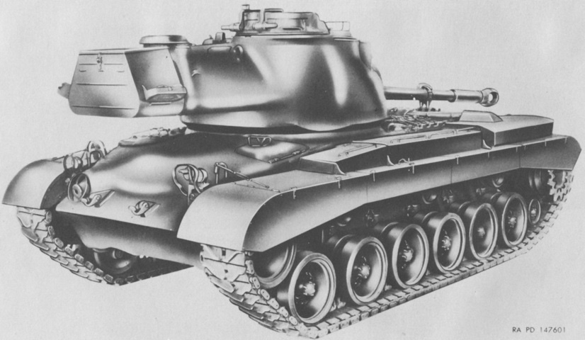
90mm Gun Tank M47 Patton 47.
The turret is reversed in this front 3/4 view, and the 90mm gun is secured in its travel lock. This early-production tank is seen with a single-baffle muzzle brake, and it lacks the stereoscopic rangefinder. (Picture from TM 9-718A 90-mm Gun Tank M47.)
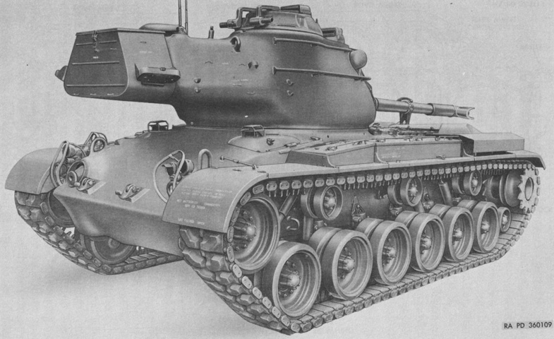
The rangefinder is present on this later-production machine, and a T-shaped blast deflector is installed. The location of the return rollers can be better seen with the dust shields absent. (Picture from TM 9-2350-200-12 Operation and Organizational Maintenance 90-mm Gun Full Tracked Combat Tank M47.)

Fixtures on the hull front are labeled. (Picture from TM 9-718A 90-mm Gun Tank M47.)
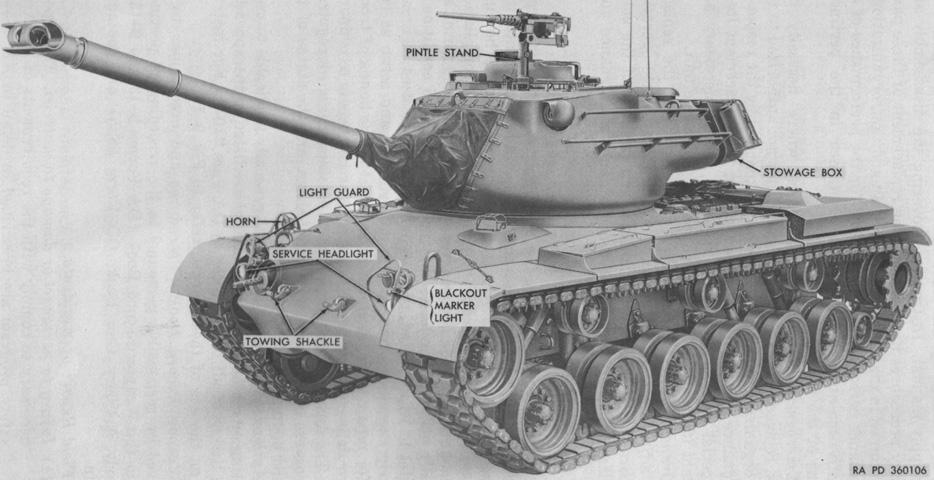
A better view of the newer blast deflector can be seen with the turret of this late-production tank trained to the front. The rooftop machine gun pintle has been moved to a location that eased use. (Picture from TM 9-2350-200-12 Operation and Organizational Maintenance 90-mm Gun Full Tracked Combat Tank M47.)
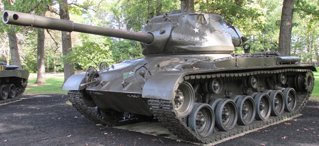
This tank is fitted with the later cylindrical blast deflector, and is missing its rangefinder and rear compensating idler wheel. The port in the gun shield for the coaxial machine gun has been plated over.
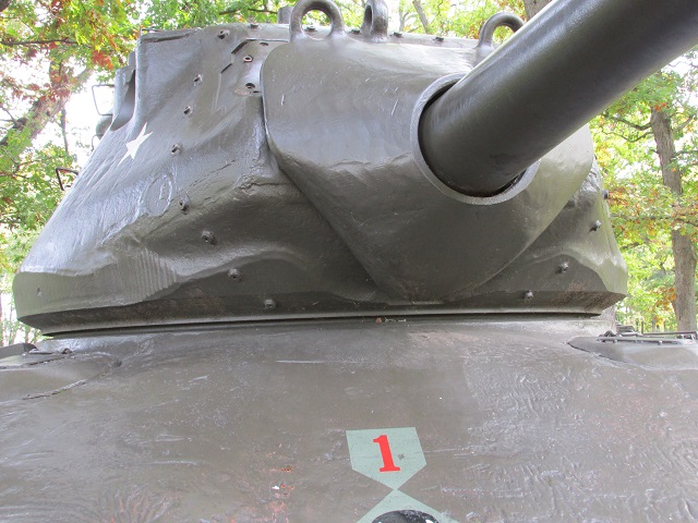
Contours of the turret and gun shield can be seen in this image, along with the absence of the ventilator that was present between the drivers on the M26 and M46. The gunner did not have a sighting telescope; the stereoscopic rangefinder was his primary sight and his periscope was his secondary sight.
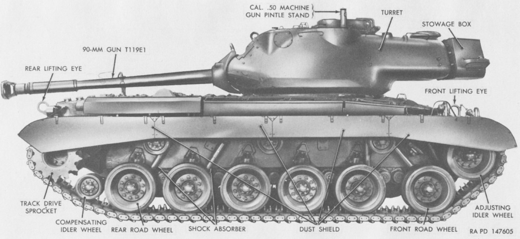
The long turret bustle, or "bulge," can be seen here, which was elongated further with the addition of a stowage box at the end. This early-production tank is not fitted with the rangefinder, and the blanked off apertures for the rangefinder can be seen at the top of the turret near the front. (Picture from TM 9-718A 90-mm Gun Tank M47.)
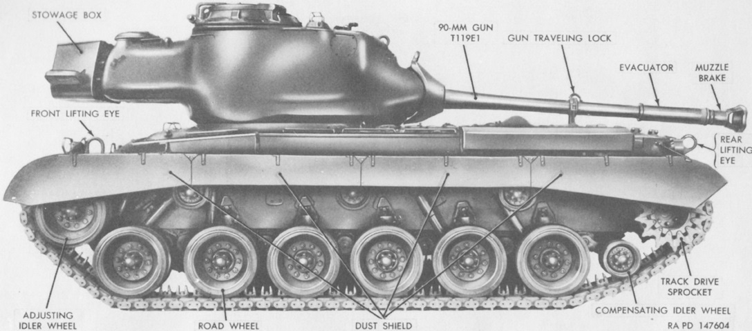
The vehicle's opposite side is shown here. (Picture from TM 9-718A 90-mm Gun Tank M47.)
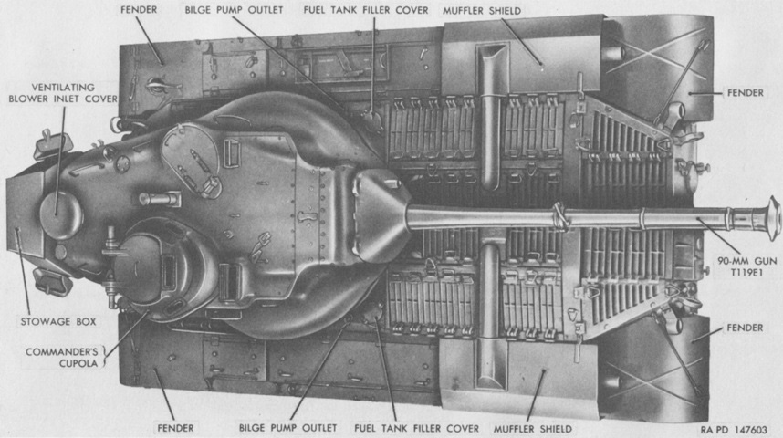
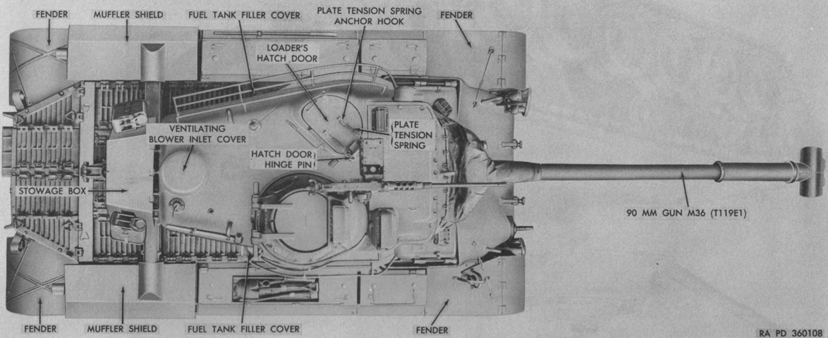
Details of the top of the vehicle are seen in this image. (Picture from TM 9-718A 90-mm Gun Tank M47.)
The more forward position of the .50cal machine gun pintle mount and the blast deflector shape can be contrasted with the image above. (Picture from TM 9-2350-200-12 Operation and Organizational Maintenance 90-mm Gun Full Tracked Combat Tank M47.)
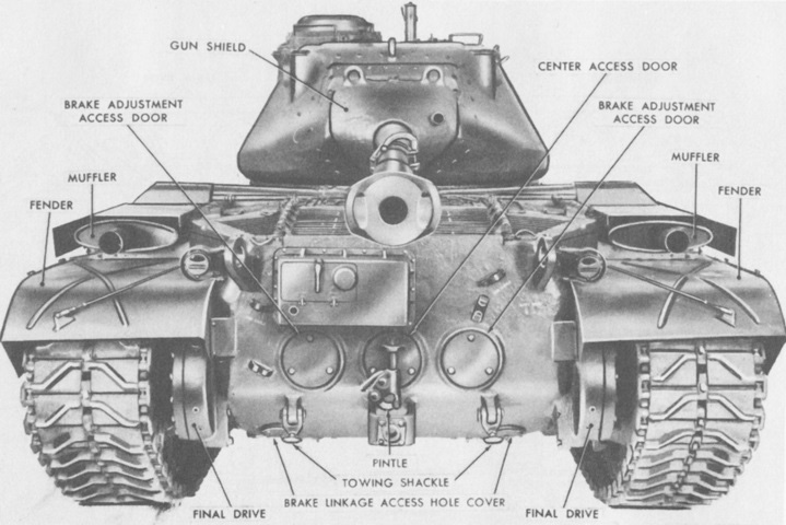
Details of the rear of the vehicle are seen in this image. (Picture from TM 9-718A 90-mm Gun Tank M47.)
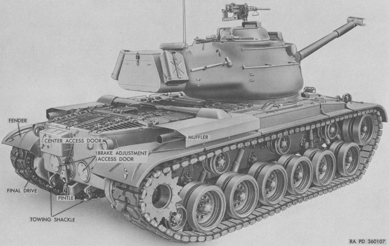
A late-production vehicle is seen from the right rear. (Picture from TM 9-2350-200-12 Operation and Organizational Maintenance 90-mm Gun Full Tracked Combat Tank M47.)
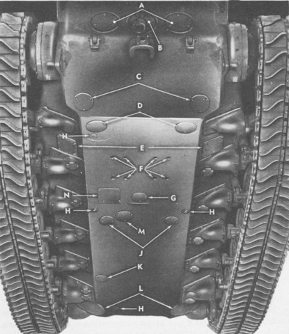
Openings in the hull bottom are labeled here. A. Side access door. B. Center access door. C. Brake linkage access hole cover. D. Transmission drain access hole cover. E. Oil cooler service hole cover. F. Engine mounting bolt hole. G. Main engine drain access hole cover. H. Drain valve. J. Fuel tank drain access hole cover. K. Hull drain hole cover. L. Escape hatch door. M. Main engine oil filter access hole cover. N. Main generator access hole cover. (Picture from TM 9-718A 90-mm Gun Tank M47.)
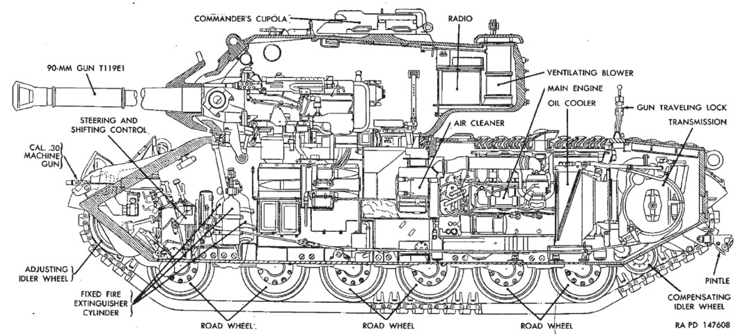
The tank's interior arrangement is shown in this sectionalized view. As shown here, some early-production tanks were fitted with a .50cal coaxial machine gun. (Picture from TM 9-718A 90-mm Gun Tank M47.)
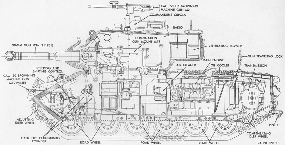
A .30cal coaxial machine gun is mounted in this sketch. (Picture from TM 9-2350-200-12 Operation and Organizational Maintenance 90-mm Gun Full Tracked Combat Tank M47.)
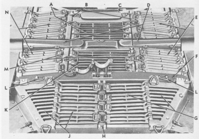
The rear deck is isolated here. A. Front grille door. B. Front grille door support. C. Center battery box cover. D. Exhaust pipe housing cover. E. Right grille door. F. Rear crossbeam. G. Right rear grille door. H. Rear grille door support. J. Left rear grille door. K. Intermediate grille door. L. Lifting loop. M. Intermediate grille door support. N. Left grille door. (Picture from TM 9-718A 90-mm Gun Tank M47.)
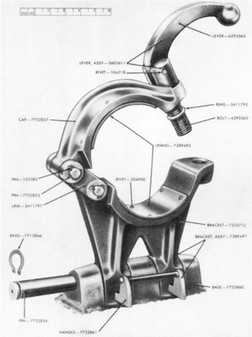
The gun travel lock is detailed in this image. (Picture from ORD 9 SNL G-262 List of All Service Parts of Tank, 90-mm Gun, M47.)
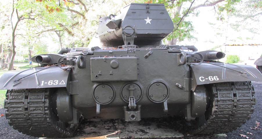
The components and access doors of the rear can be better seen on this real machine; note the taller gun travel lock. This tank was fitted with the rubber T84E1 tracks, which have worn away.
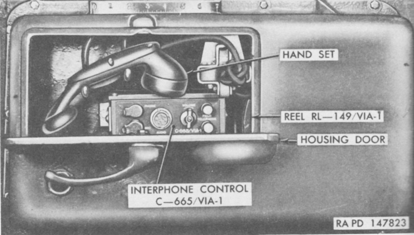
On the hull rear above the left brake adjustment access door and the center access door was mounted the housing for the auxiliary interphone equipment AN/VIA-1. This allowed dismounts to communicate with the tank crew. On the lower left corner of the housing, partially hidden by the access door handle, is a light that the loader could flash to signal external personnel. (Picture from TM 9-718A 90-mm Gun Tank M47.)
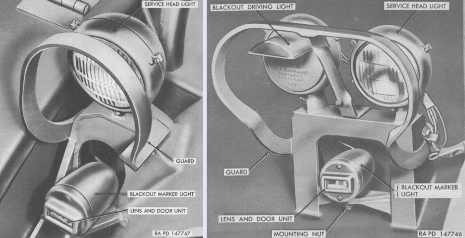
The right and left headlight clusters of an early tank are labeled on the left and right, respectively. The blackout driving light provided a dim, downward-directed light for tactical driving in low light conditions. (Picture from TM 9-718A 90-mm Gun Tank M47.)
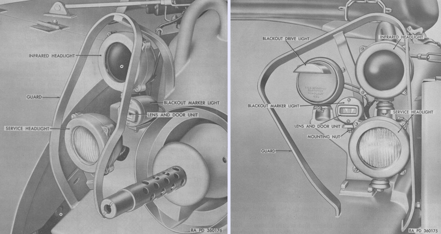
With the fielding of the infrared periscope M19, infrared headlights were added. The driver could replace the normal periscope M13 with the infrared periscope M19, and this would convert the reflected infrared rays projected from the infrared headlights into a visible image. (Picture from TM 9-2350-200-12 Operation and Organizational Maintenance 90-mm Gun Full Tracked Combat Tank M47.)
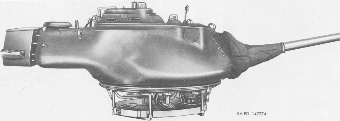
The turret basket can easily be seen with the turret dismounted from the hull. The large bulge was used to counterbalance the weight of the 90mm gun. (Picture from TM 9-718A 90-mm Gun Tank M47.)
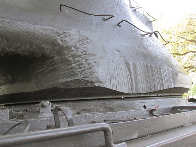
Substantial machining was performed on the sides and rear corners of this turret. Tool stowage was provided on the fender in the foreground.
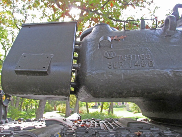
Attachment of the turret stowage box is highlighted here. An antenna mount and the opening for the ventilating blower can be seen on the roof of the turret bulge.
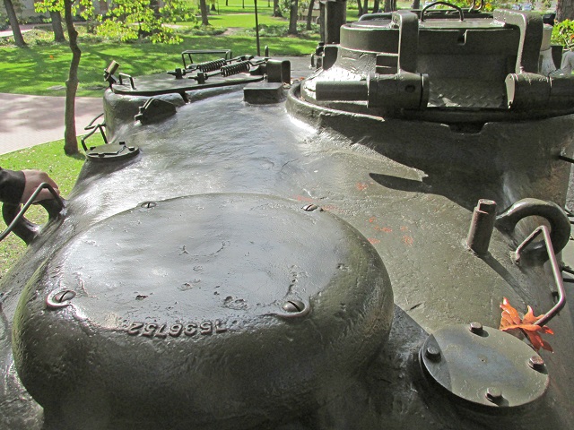
The rounded nature of the top of the turret bulge can be gleaned from this image. The ventilator blower is in the foreground, and next to it is an antenna mount. A second antenna mount can be seen on the left side of the turret.
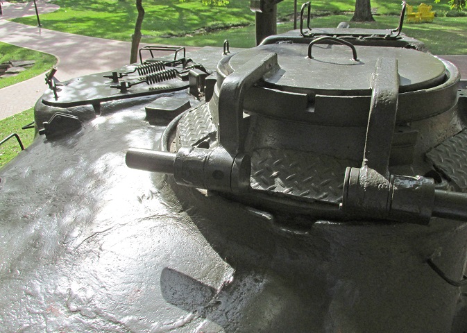
A closer look at the rear of the cupola shows where vision blocks would be visible if not covered by diamond plate. The loader's hatch opened to the front, and assisting springs can be seen connecting it to the roof.
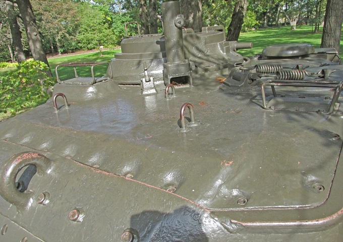
Looking at the turret roof, there is a large removable plate above the rangefinder and gunner's periscope. The loader's fixed periscope can be seen on the right of the image, and the commander's later-style cupola is behind the machine gun pintle stand, which was heightened and relocated from its original spot.
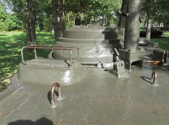
The position of the gunner's periscope in front of the commander's cupola is seen here. On earlier tanks, the .50cal machine gun pintle stand was farther back on the turret in a less usable position.
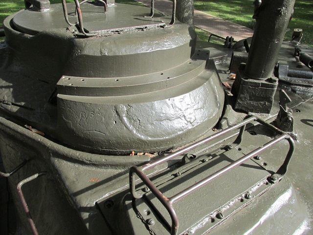
A closer view of the cupola and gunner's periscope opening illustrates their wire-type brush guards, which can be contrasted with the solid guards found on later tanks.

The cupola door is open, allowing a view into the tank's interior. The commander's seat and shell case stop assembly are visible inside. (Picture from TM 9-718A 90-mm Gun Tank M47.)
The relocated machine gun pintle mount is at the cupola's immediate front left. Periscope guards were changed from open wire types to solid covers. (Picture from TM 9-2350-200-12 Operation and Organizational Maintenance 90-mm Gun Full Tracked Combat Tank M47.)
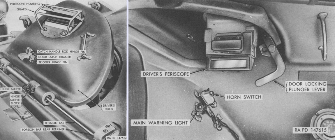
Exterior and interior controls for the driver's door are labeled in this image. (Picture from TM 9-718A 90-mm Gun Tank M47.)
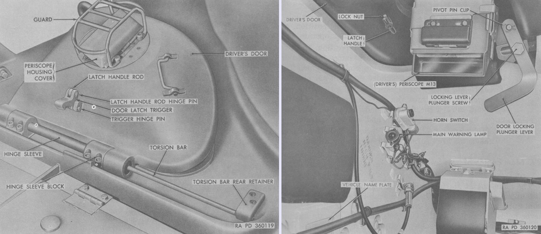
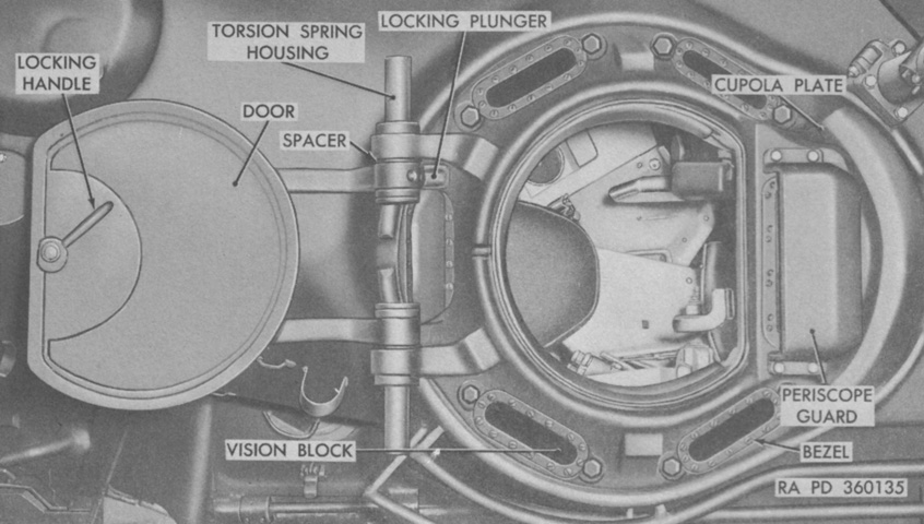
During production, the periscope guard for the drivers' doors was changed to the design seen here. (Picture from TM 9-2350-200-12 Operation and Organizational Maintenance 90-mm Gun Full Tracked Combat Tank M47.)
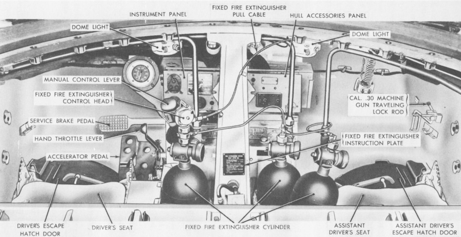
The drivers' positions and controls of an early-production tank are shown here. The bow gunner had no driving controls. (Picture from TM 9-718A 90-mm Gun Tank M47.)
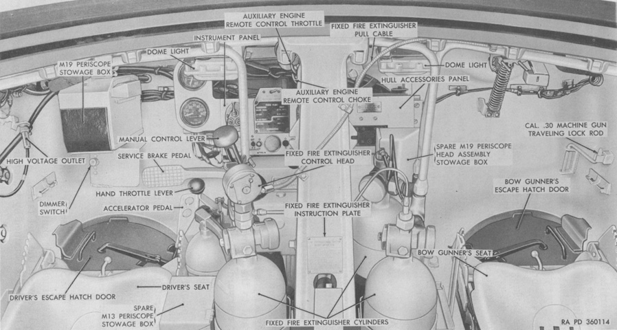
Changes in the drivers' positions for a later tank include a revised speedometer and tachometer, new dome light design, and a stowage box for an infrared periscope M19. (Picture from TM 9-2350-200-12 Operation and Organizational Maintenance 90-mm Gun Full Tracked Combat Tank M47.)
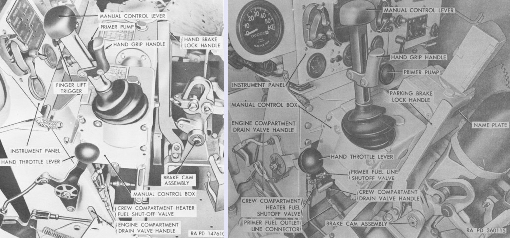
Driving controls for an early and late tank are presented on the left and right, respectively. (Picture from TM 9-718A 90-mm Gun Tank M47 and TM 9-2350-200-12 Operation and Organizational Maintenance 90-mm Gun Full Tracked Combat Tank M47.)
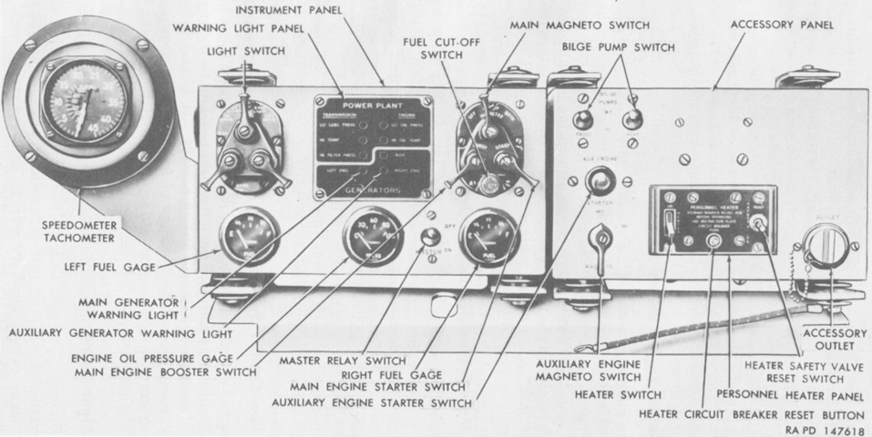
The driver's instrument panel is shown here. (Picture from TM 9-718A 90-mm Gun Tank M47.)
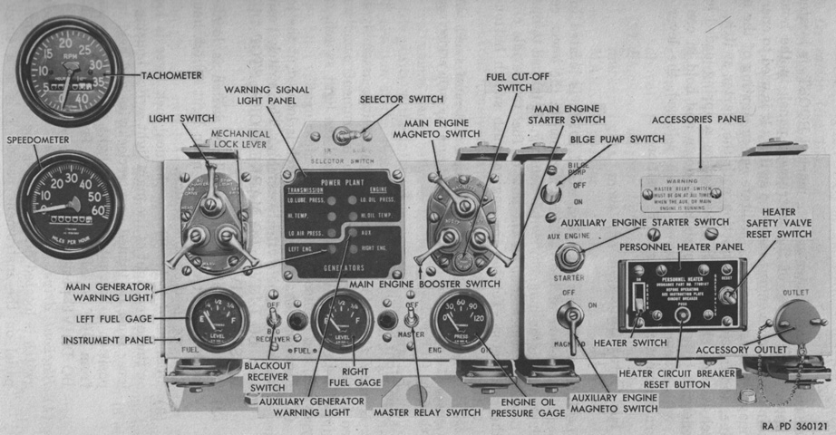
Later-production instrument panels featured changes that included separating the speedometer and tachometer indicators. (Picture from TM 9-2350-200-12 Operation and Organizational Maintenance 90-mm Gun Full Tracked Combat Tank M47.)
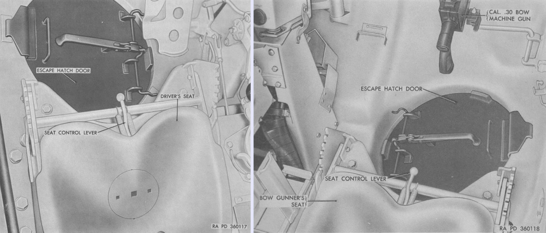
Both drivers were provided with an escape hatch in the hull floor. (Picture from TM 9-2350-200-12 Operation and Organizational Maintenance 90-mm Gun Full Tracked Combat Tank M47.)
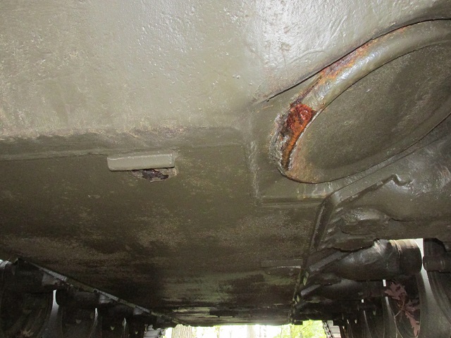
The driver's escape hatch is shown from the outside.
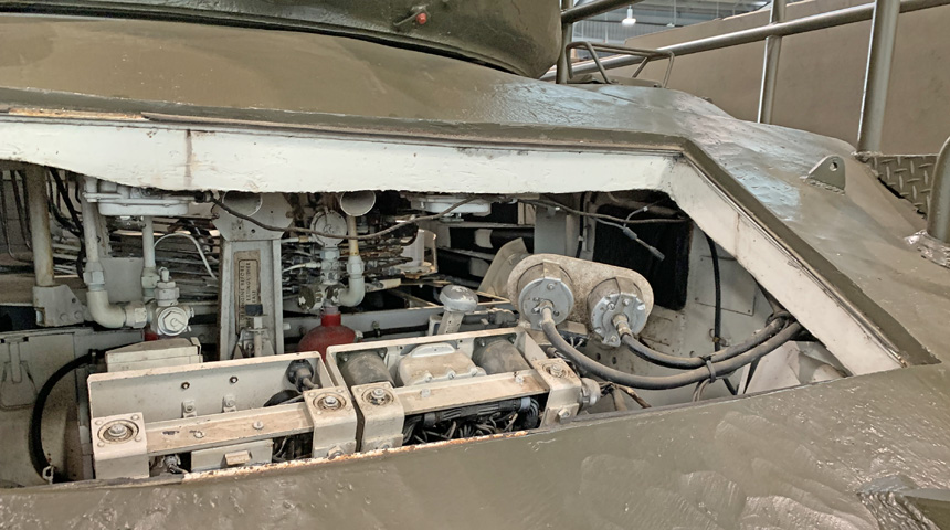
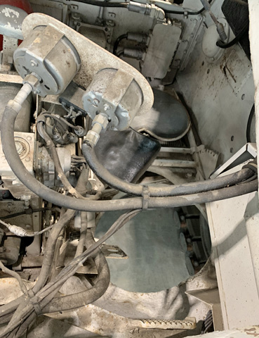
The front hull of this tank has been cut away, permitting a view of the thickness of the upper front hull as well as its internal arrangement.
The driver's seatback and floor escape hatch are absent from this machine. The seat could be locked in any of the five positions visible in the arc near the hull side wall; the horizontal control lever in front of the seat was used to move it between these positions. The service brake pedal with its nonslip texture is at the bottom of the image.
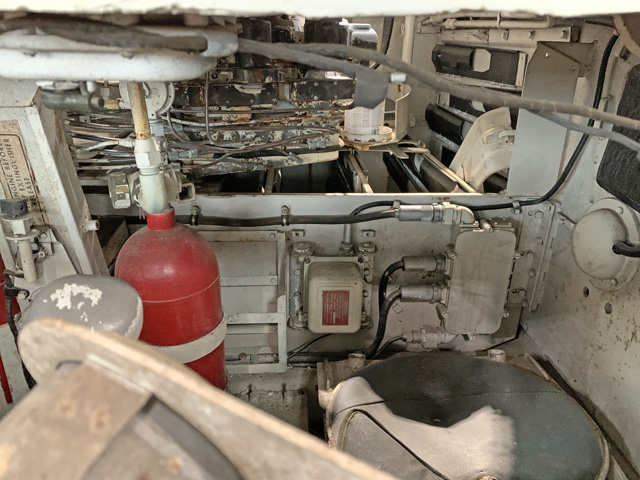
This shallower angle permits a view of the relationship between the drivers' compartment and the turret basket. The hull floor ammunition compartments are open and visible to the rear of the drivers.
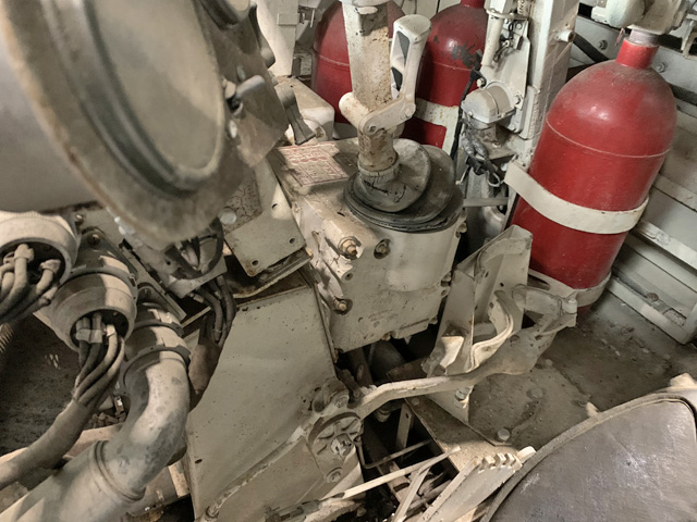
The three fixed fire extinguisher bottles are obvious in this picture. The driver's manual control lever is at the top center of the image, and the hand throttle lever is pulled down to the rear. The empty bracket for the driver's compartment portable fire extinguisher is just to the driver's right, in front of the left-most fixed fire extinguisher bottle.
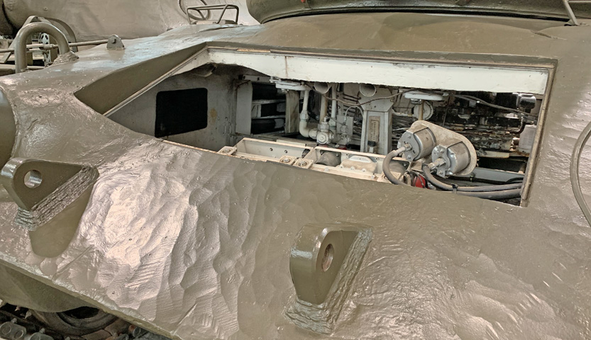
The complexity of the casting for the bow machine gun mount is apparent in this view. The rectangular frame inside the hole in the armor at one time held a window for viewing the interior.
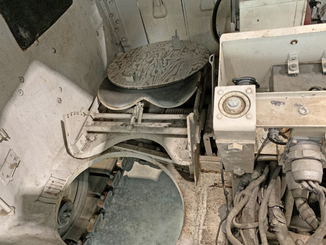
The assistant driver had no duplicated driving controls on his side of the driver's compartment. His seatback is also missing, and the circular wooden panel resting on the seat may have been a display stand-in for the assistant driver's escape hatch.
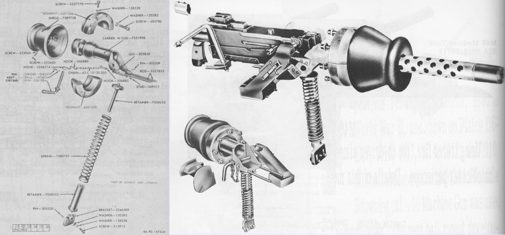
An exploded view of the assistant driver's .30 caliber ball mount 7351999 is shown on the left, and on the right the assembled mount is seen at the top and bottom from the front and rear, respectively. Compared to earlier ball mounts, the 7351999 featured an improved shield, and the front of the cradle was screwed into the shield instead of being bolted. The ammunition box was next to the mount, and a feedway guide was used to help lead the ammunition belt into the gun's chamber. The machine gun was still secured by its forward mounting holes, and an expended link chute, expended case collection bag, travel lock, and equilibrator spring were included. (Picture from Weapon Mounts for Secondary Armament.)
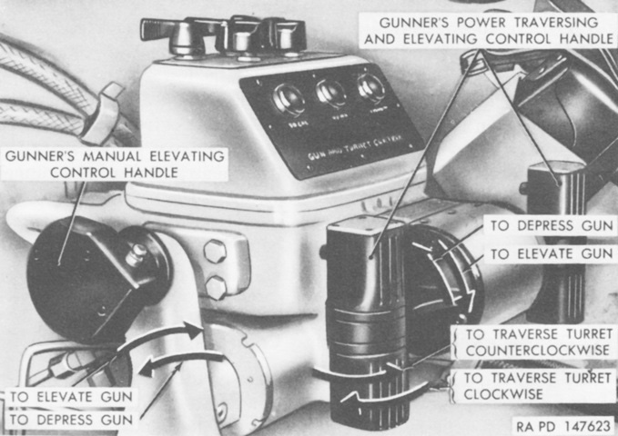
The gunner's control handles and their actions are shown here. Firing triggers can be seen on the font of the power traversing and elevating control handles, and facing upwards on the handgrip of the manual elevating control handle. (Picture from TM 9-718A 90-mm Gun Tank M47.)

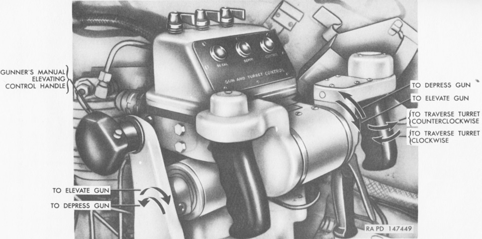
A closer view of the gunner's controls are shown here. The elevation and traverse adjusting knobs were used to adjust the speed of elevation and traverse. The knob in the lower right of the picture is the elevation cylinder control valve, used to supercharge the elevation cylinder when shifting from power to manual turret operation. (Picture from TM 9-718A 90-mm Gun Tank M47.)

A later version of the gunner's controls is illustrated in this picture. The hand drive was the manual turret traverse. When the release lever on the manual traverse handle was squeezed, the dump valve was actuated to remove hydraulic power from the traversing mechanism and engage the manual drive gears.
The action of the the no-back mechanism is detailed on the right. It protected the gunner and the traversing mechanism by holding the turret in position and preventing it from drifting if the tank was on a slope. The lock bar could be rotated in the lock ring if it was centered, and would bind on the lock ring if it was driven in an off-center position. The lock bar retained the proper centered position when it was driven by the drive bearing, but a spring forcing the lock bar off-center away from the driven bearing would cause the lock bar to lose its centered position when driven on its opposite side by that bearing, and binding action would occur. A slip clutch protected the mechanisms and operator from heavy turret impacts. It would slip when a torque of 650lb-in (73N-m) was introduced at the no-back lock bevel gear. (Picture from Manuscript of TM 9-718A C1 and TM 9-1730E Hydraulic Turret-traversing and Gun-elevating system for 76-mm. Gun Tank T41E1 and 90-mm. Gun Tank M47.)
The operation of the hydraulic control handles as well as the manual elevation handle is shown here. Traverse was accomplished by turning the right handle to the left or right, and elevation by pushing or pulling the top of the handle away from or towards the gunner. Maximum displacement of the handle in traverse would close a microswitch that removed the pulsing relay circuit and increased the traverse speed to its maximum slew speed of 4rpm from the maximum tracking speed of 1.7rpm. The left handle was a dummy handgrip, although both handles featured firing triggers on their front faces. The right handle could be rotated 30° about both the traversing and elevating axes, and there was a 3° neutral zone about each axis. (Picture from Manuscript of TM 9-718A C1.)
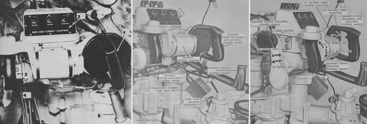
Even later in production, the gunner's controls were changed to those seen here. The right vertical handle was replaced by a round, enclosed handle design. To traverse the turret, the handle was rotated clockwise or counterclockwise. The legend for the left image is: 1. Gunner's power control handle. 2. Turret power control box. 3. Hand grip (dummy). 4. Manual elevation control handle. 5. Manual traverse control handle. (Picture from FM 17-78 Tank, 90-mm Gun, M47 and TM 9-2350-200-12 Operation and Organizational Maintenance 90-mm Gun Full Tracked Combat Tank M47.)
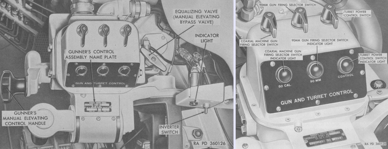
The revised gun and turret control switch housing is shown above. Notably, the traverse and elevation speed adjustment knobs have been omitted; as the gunner's and commander's turret controls always regulated these speeds by the amount of handle displacement from center, these knobs may have been considered redundant. (Picture from TM 9-2350-200-12 Operation and Organizational Maintenance 90-mm Gun Full Tracked Combat Tank M47.)
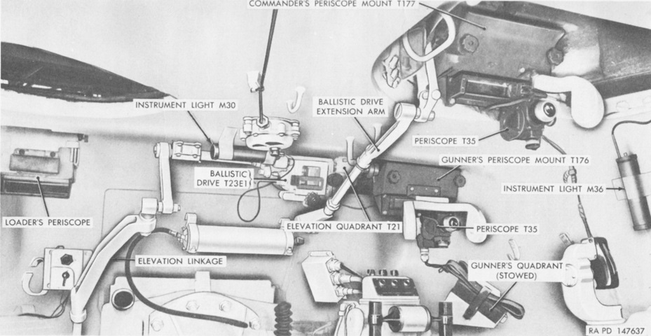
The front wall of the turret is the subject of this image. This early tank was not fitted with the stereoscopic rangefinder, so the periscope T35 was substituted as the main gunnery sight. Many of these components were later standardized: the periscope T35 as M20; the elevation quadrant T21 as M13; the ballistic drive T23E1 as M3; the periscope mount T176 as M88; periscope mount T177 as M89. (Picture from TM 9-718A 90-mm Gun Tank M47.)
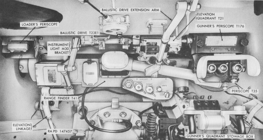
This later-production vehicle does have the rangefinder installed, and the linkage connections can be contrasted with the early machine. (Picture from Manuscript of TM 9-718A C1.)
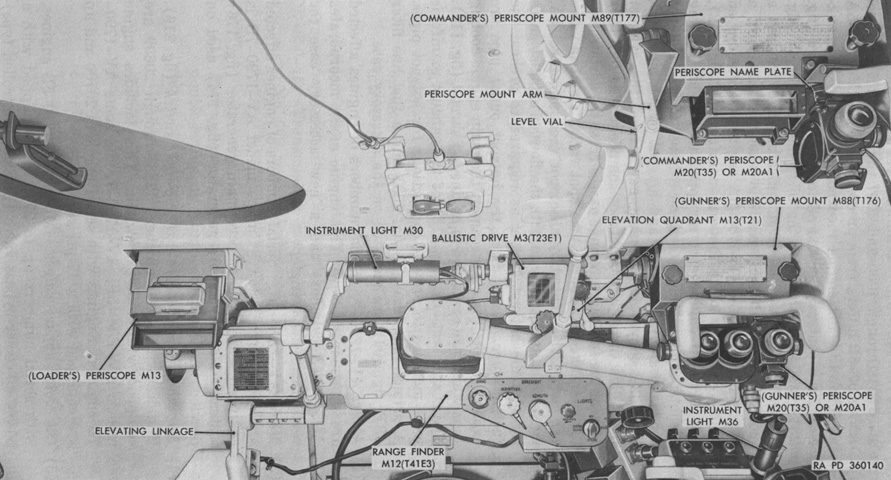
Another view of the late fire control system is provided with both designations of the instruments. Note the new design of dome light on the turret roof. (Picture from TM 9-2350-200-12 Operation and Organizational Maintenance 90-mm Gun Full Tracked Combat Tank M47.)
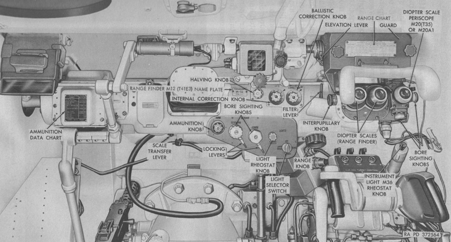
Controls for the sighting and fire control instruments are labeled in this image. (Picture from TM 9-2350-200-12 Operation and Organizational Maintenance 90-mm Gun Full Tracked Combat Tank M47.)
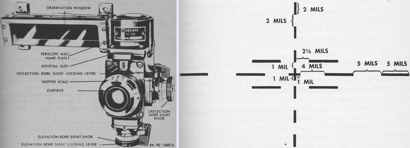
The gunner and commander were each provided with a periscope M20, which had a unity window and a 6x magnification telescope for sighting. The "sagebrush" gun laying reticle of the 6x system is sketched on the right; the 1x system had no reticle. The field of view through the unity window was 33°18' horizontal and 7°9; vertical, while the 6x telescope had an 8° field of view. The gunner's periscope was the secondary direct fire sight when the rangefinder was installed. The commander's served as a target designate device, and could be used as a direct fire sight in an emergency. (Picture from FM 17-78 Tank, 90-mm Gun, M47.)
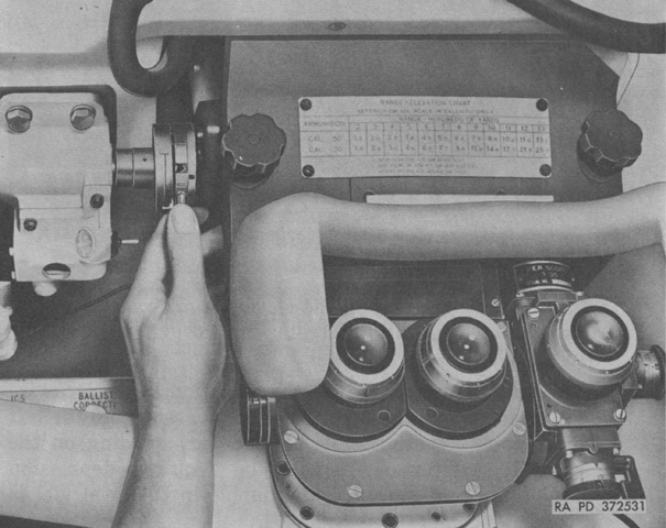
If desired, the vertical line of sight of the periscope M20 could be temporarily altered by turning the elevation lever as shown. When the lever was released, the periscope head would return to its normal position. (Picture from TM 9-2350-200-12 Operation and Organizational Maintenance 90-mm Gun Full Tracked Combat Tank M47.)
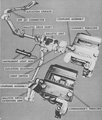
The ballistic drive is shown here without the rangefinder installed. The commander's and gunner's periscopes were connected to the main gun so that their mirrors followed the gun when it was elevated or depressed. However, when the rangefinder was mounted it was connected to the gun through the ballistic drive, and the gunner's periscope was in turn connected to the rangefinder. A sprung lever on the coupler allowed the periscope head mirror to be manually independently elevated up to 22° from zero elevation, which would increase the amount of terrain visible while scanning without elevating the gun. Rotating the range drum of the ballistic drive introduced superelevation for range and ammunition type when the periscopes were used for laying the gun. (Picture from FM 17-78 Tank, 90-mm Gun, M47.)
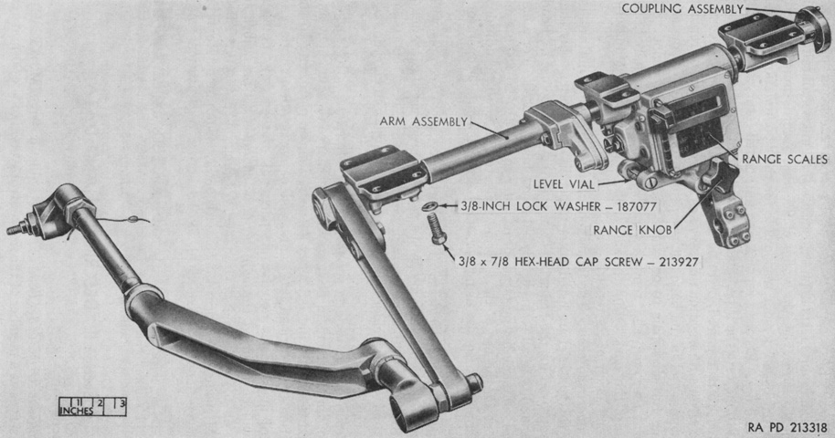
The ballistic drive M3 is isolated in this image. It was 33½" (85.1cm) long, 22" (56cm) wide, 29⅝" (75.248cm) high, and weighed 40 pounds (18kg). Its range scales included 90mm high-explosive, 90mm HVAP, 90mm APC, 90mm HEAT, and a mil scale. (Picture from TM 9-6065 Ordnance Maintenance Ballistic Drives M3 (T23E1), M4 (T23), T23E2 and T24.)
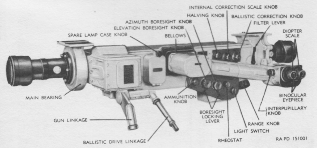
The rangefinder M12 was the primary direct-fire sight when installed. The gunner operated the rangefinder and indexed the chosen ammunition type. The scales and reticle were in the left eyepiece, while the stereoscopic pattern was viewed through both eyepieces. The rangefinder was connected electrically to the superelevation transmitter M22, which was located on the powerpack. When turret power was on, the M22 automatically applied superelevation to the gun and kept the ranging pattern in contact with the target. The M12 was 64.75" (164.5cm) long overall with a 60" (150cm) base length, 25.375" (64.453cm) deep, 28.0" (71.1cm) tall, and weighed 270lb (120kg). Magnification was 7.5x, and field of view was 5°. (Picture from Manuscript of TM 9-718A C1.)
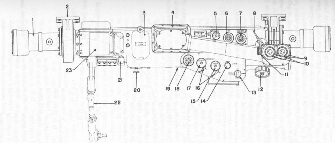
A schematic of the rangefinder is shown here. 1. End box. 2. Main bearing. 3. Spare lamp case. 4. Bellows. 5. Halving knob. 6. Internal correction system knob. 7. Ballistic correction knob. 8. Filter lever. 9. Diopter scale. `10. Binocular eyepiece. 11. Interpupillary knob. 12. Range knob. 13. Four-position light switch. 14. Rheostat. 15. Azimuth boresight knob. 16. Boresight knob locking levers. 17. Elevation boresight knob. 18. Ammunition knob. 19. Scales transfer lever (not visible). 20. Reticle lamp replacement knob. 21. Linkage to ballistic drive. 22. Linkage to gun. 23. Position of ammunition data chart. (Picture from FM 17-78 Tank, 90-mm Gun, M47.)
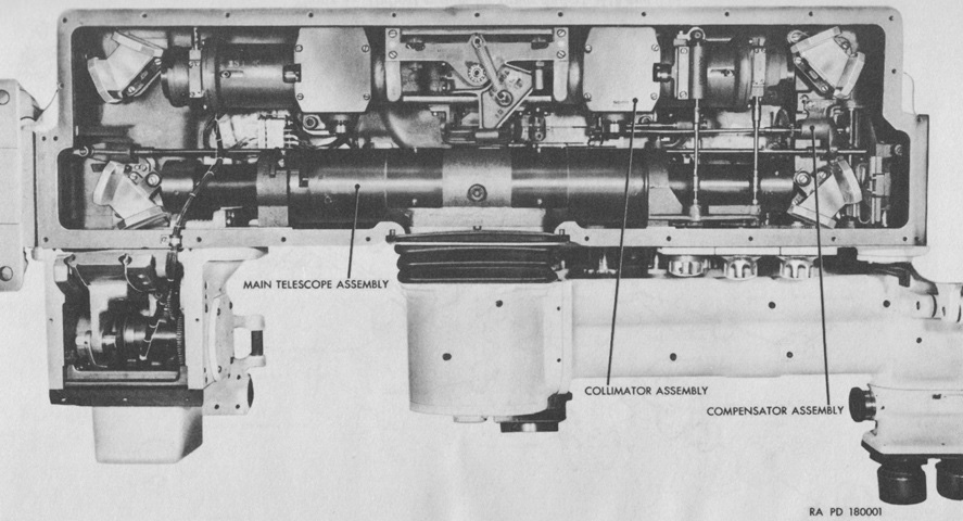
The rangefinder is seen here from above with the cover removed. The collimator assembly received and projected illuminated images of the range and ammunition scales and gunlaying reticles. During normal ranging, the scale transfer prism deflected the images to the left eyepiece, but the stereoscopic reticles were viewed through both eyepieces. The compensator assembly optics consisted of a movable positive lens and a stationary negative lens that served as a variable range wedge. The movable lens was mounted in a sliding holder that was controlled by the range knob. (Picture from TM 9-6067 Ordnance Maintenance Range Finders M12 and T41.)
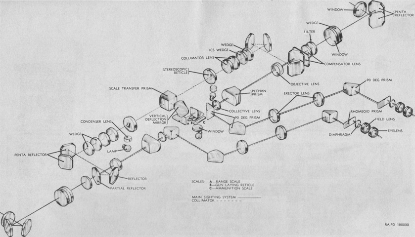
A schematic of the rangefinder's optical system is drawn in this image. (Picture from TM 9-6067 Ordnance Maintenance Range Finders M12 and T41.)
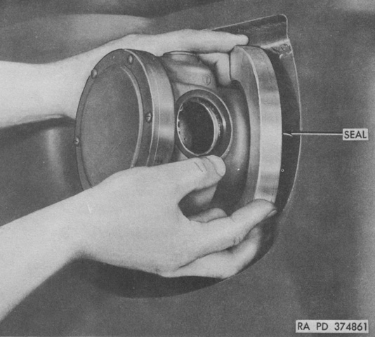
Each end housing assembly of the rangefinder was surrounded by a two-part seal that secured the turret openings. (Picture from TM 9-2350-200-12 Operation and Organizational Maintenance 90-mm Gun Full Tracked Combat Tank M47.)
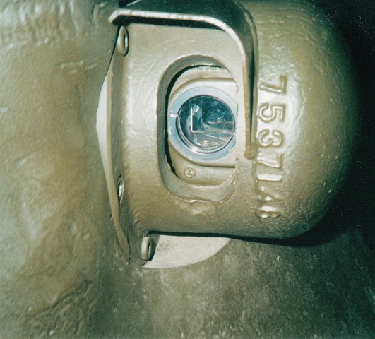
This picture is of the left-hand M12 rangefinder end box blister. The M12 was a stereoscopic rangefinder, and while having the potential of being more accurate than a coincidence rangefinder, the visualization process of aligning the lowest mark so that it appeared to be at a similar range as the target (a procedure tankers dubbed "flying the geese") is difficult for a percentage of the population, and this type of rangefinder was replaced on the M48A2C tank with a more user-friendly coincidence type. Each blister was attached to the turret by six ½ x 1¼ hex socket bolts.
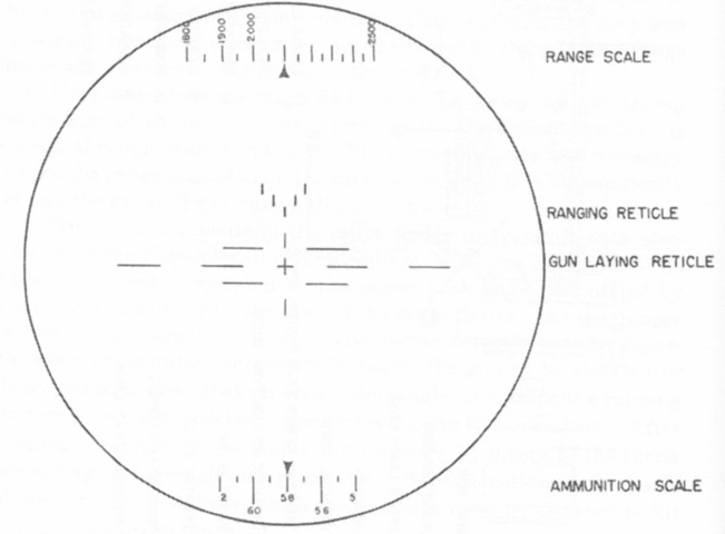
This sketch represents the rangefinder reticle. The range scale was graduated from 500 to 5,000 yards (460 to 4,600m), and the estimated range could be indexed on the range scale if the rangefinder was being used as a telescope instead of a rangefinder (e.g., due to damage). A ranging reticle was present in each eyepiece, and the halving knob was used to make these appear at the same elevation. This fused the reticle images into one, with the bottom mark appearing farthest away, the two center marks closer than the bottom, and the two top marks closest of all. The reticle would appear to move farther away as the range knob was used to increase the range on the range scale. When the lowest mark of the reticle appeared to be at the same range as the target, the range was then found. The ammunition scale at the bottom was graduated from 0 to 90. An ammunition data chart was attached to the rangefinder, and the appropriate value was referenced and dialed in depending on the type of ammunition being used. Once the target was ranged, the center aiming cross of the gun laying reticle was placed on the center of the target unless a lead was necessary. (Picture from FM 17-78 Tank, 90-mm Gun, M47.)
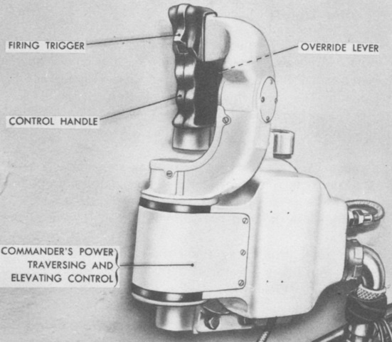
The commander was also provided with a power traversing and elevating control handle. The TC could override the gunner's inputs by squeezing the override lever against the control handle. Traverse was accomplished by turning the handle in the desired direction, and elevation was done by turning the top of the handle towards the front or rear of the turret. The handle could be rotated 30° in both the horizontal and vertical axes, and had a 3° neutral zone in each direction. (Picture from TM 9-718A 90-mm Gun Tank M47.)
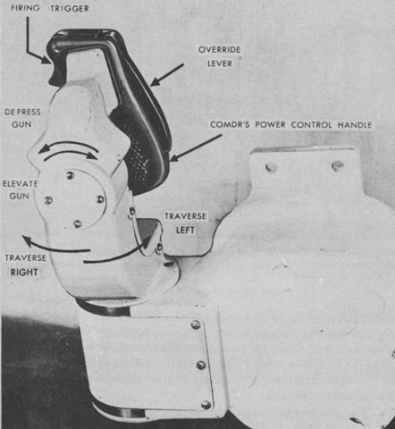
The override lever can be seen here on the back of the control handle. The override control box contained relays that, once energized by squeezing the override lever, transferred elevation, traverse, and firing control from the gunner's controls to the commander's control handle. (Picture from FM 17-78 Tank, 90-mm Gun, M47.)
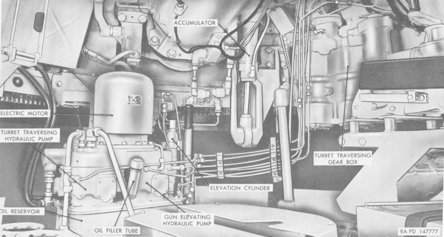
The hydraulic system for the turret was situated mainly under the gun breech at the front of the turret basket. The gunner's position is to the upper right of the image. Note that the captions for the elevation cylinder and the accumulator have been reversed in this picture. (Picture from TM 9-718A 90-mm Gun Tank M47.)
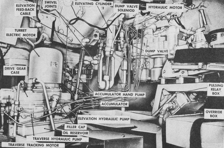
A more detailed view is provided of a later-production tank. (Picture from FM 17-78 Tank, 90-mm Gun, M47.)
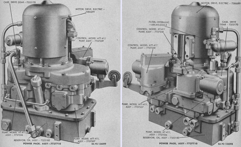
Front and rear views of the turret power pack are at the left and right, respectively. It essentially consisted of an A.O. Smith Model D-9004 compound-wound 5-horsepower 24-volt DC electric drive motor; drive gears inside of a case; an Oilgear Model AT-411 traversing pump with a Minneapolis-Honeywell Model G-2059A1 signal motor and feedback-operated differential control; another AT-411 for elevation with a signal motor or rangefinder and feedback-operated dual differential control; and an oil reservoir and hydraulic filter. The powerpack's net weight was 266lb (121kg), with the electric drive motor making up 85lb (39kg) of that total, the traversing AT-411 pump 65lb (29kg), the elevating AT-411 71lb (32kg), and the 1½gal (5.7L) capacity oil reservoir 31lb (14kg). (Picture from TM 9-1730E Hydraulic Turret-traversing and Gun-elevating system for 76-mm. Gun Tank T41E1 and 90-mm. Gun Tank M47.)
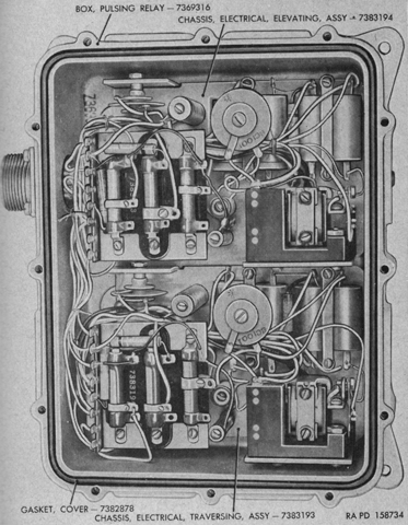
The innards of the pulsing relay box are revealed. The pulsing relay box regulated the speed of the elevating and traversing signal motors in conjunction with the gunner's or commander's control handles. Polarized pulsing relays were generated that closed contacts when the relays flowed in one direction and opened contacts when flowing in the opposite direction. A single set of make-and-break contacts controlled the current flow through the signal motor fields and armatures. Speed regulation was accomplished by varying the amount of time the contacts were closed by increasing the impedance of the closing path the farther the control handle was moved. (Picture from TM 9-1730E Hydraulic Turret-traversing and Gun-elevating system for 76-mm. Gun Tank T41E1 and 90-mm. Gun Tank M47.)
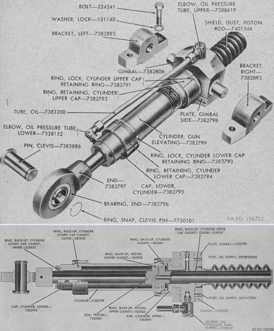
Exploded and cross-sectional views of the gun mount elevation cylinder are at the top and bottom, respectively. Manufactured by Bendix Aviation Corporation's Pacific Division, it was a double-acting, non-differential hydraulic cylinder that both elevated and depressed the gun. Its lower end was attached to the lower edge of the turret by a clevis pin, and its upper end was mounted in gimbals attached to the gun by mounting brackets. Separate oil lines were used for elevation and depression. The cylinder was 30" (76cm) long, 9" (23cm) wide over the brackets, and its operating pressure was 2,000psi (141kg/cm²). (Picture from TM 9-1730E Hydraulic Turret-traversing and Gun-elevating system for 76-mm. Gun Tank T41E1 and 90-mm. Gun Tank M47.)
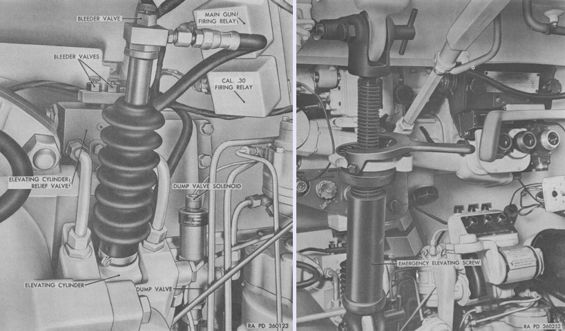
The elevation cylinder is installed on the left. If the hydraulic system failed, an emergency elevating screw could be attached to the gun mount bracket and turret roof as shown on the right. The gunner could then manually elevate and depress the gun. When not in use, the emergency elevating screw was stowed under the commander's footrest. (Picture from TM 9-2350-200-12 Operation and Organizational Maintenance 90-mm Gun Full Tracked Combat Tank M47.)
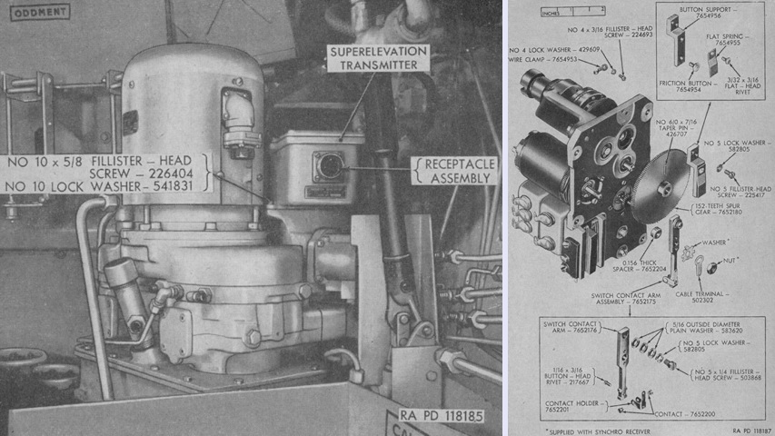
The superelevation transmitter M22 is seen on the left in place on the turret hydraulic power unit. It was shared with the 120mm gun tank M103, and essentially consisted of a synchro-torque receiver, a multiple-contact switch, a servo motor, and a geared coupling drive. The M22's synchro-torque receiver was electrically synchronized with the synchro-torque transmitter found in the rangefinder, so that any movement of the transmitter's rotor would result in a similar movement in the receiver's rotor. The receiver's rotor had an arm directly attached to it that was connected to the power source, so that movement of the rotor would swing the arm assembly points into contact with the switch's points. The switch operated the servo motor, which was geared to a coupling that was linked to the gun's elevation hydraulic system. The innards of the M22 are partially exploded on the right; the coupling to the hydraulic system is at the upper rear of the device. (Picture from TM 9-6073 Ordnance Maintenance Superelevation Transmitter M22.)
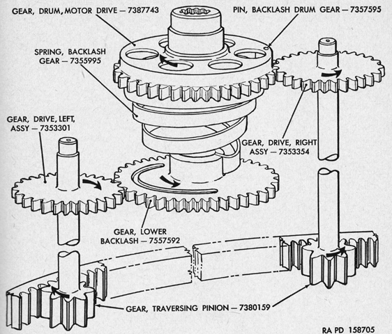
A counterclockwise-wound backlash spring was connected to the motor drive drum gear via the backlash drum gear pin. This spring exerted a counterclockwise torque against the right drive gear. Similarly, the lower backlash gear connected to the spring by a slot in the gear hub, causing it to exert a clockwise torque on the left drive gear. The drive gears were connected to the traversing pinion gears that meshed with the turret ring, and therefore a constant antilash torque was applied to these gears, eliminating lash between the traverse pinions and turret ring as well as all meshing gears in the traversing mechanism's planetary gear reduction systems. (Picture from TM 9-1730E Hydraulic Turret-traversing and Gun-elevating system for 76-mm. Gun Tank T41E1 and 90-mm. Gun Tank M47.)
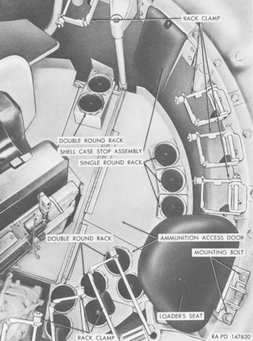
A view is provided through the open loader's hatch on the left, and his position and eleven-round 90mm ammunition ready racks are shown on the right. Note the .50cal coaxial machine gun. (Picture from TM 9-718A 90-mm Gun Tank M47.)
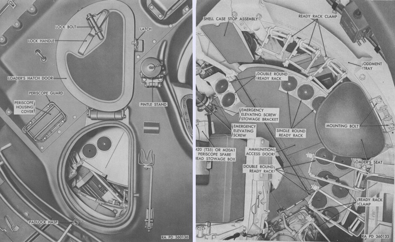
No coaxial machine gun is mounted in this later tank, but the revised position for the roof machine gun pintle is obvious. (Picture from TM 9-2350-200-12 Operation and Organizational Maintenance 90-mm Gun Full Tracked Combat Tank M47.)
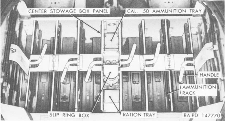
The ammunition stowage boxes in the hull floor have been opened in this image. (Picture from TM 9-718A 90-mm Gun Tank M47.)
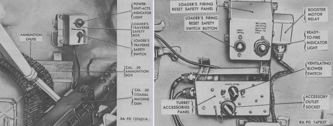
The loader's controls in an early-production tank are shown here. In the left image, the traverse safety box allowed the loader to interrupt power to the elevation and traverse systems. The light on the box illuminated when power to the systems was on. In the right image, the firing reset safety switch opened and closed the 90mm gun electrical firing circuit. It was reset by pushing the switch button, and its light illuminated when the 90mm gun was ready to be fired. (Picture from TM 9-718A 90-mm Gun Tank M47.)
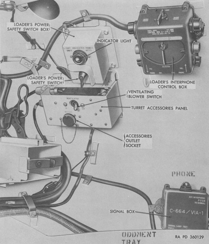
The power safety switch box was relocated to the turret side wall in later tanks, and the firing safety reset panel was removed. (Picture from TM 9-2350-200-12 Operation and Organizational Maintenance 90-mm Gun Full Tracked Combat Tank M47.)
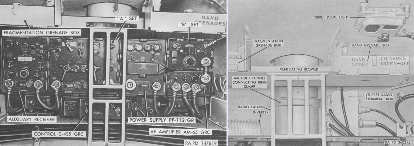
The turret rear is seen on the left with an AN/GRC-3 radio set installed, and without a radio on the right. (Picture from TM 9-2350-200-12 Operation and Organizational Maintenance 90-mm Gun Full Tracked Combat Tank M47.)
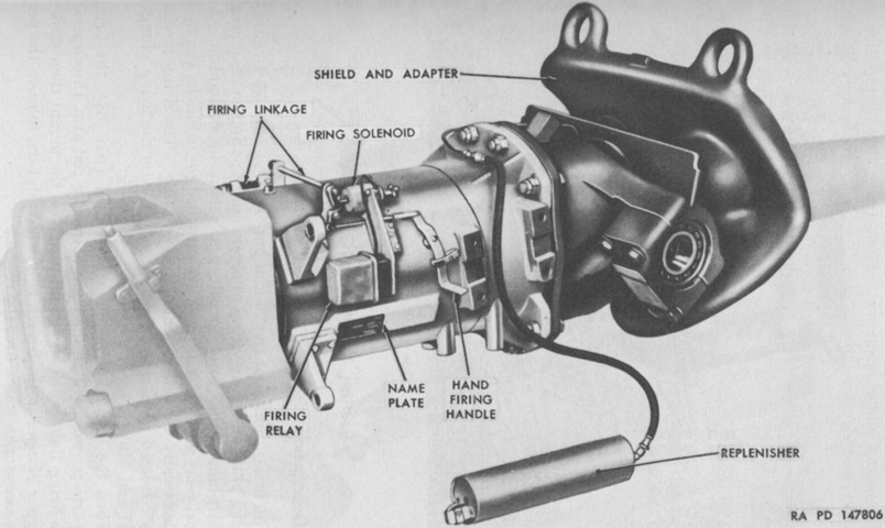
The combination gun mount M78 is shown from the right. It included a concentric hydrospring recoil mechanism with a capacity of 6 gallons (23L) of fluid including the replenisher, and normal and maximum recoil lengths of 12" (30cm) and 14" (36cm), respectively. The mount weighed ~2,000lb (~900kg). (Picture from TM 9-718A 90-mm Gun Tank M47.)
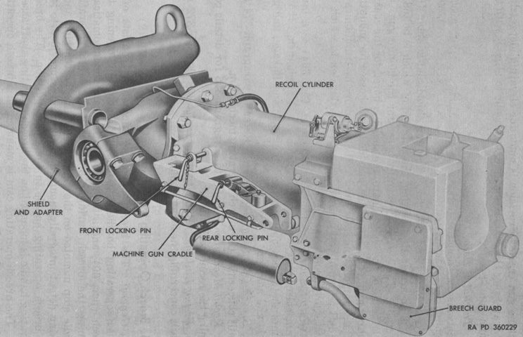
The opposite side of the gun mount is seen. (Picture from TM 9-2350-200-12 Operation and Organizational Maintenance 90-mm Gun Full Tracked Combat Tank M47.)
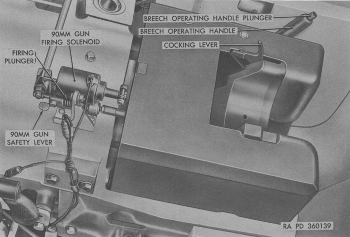
Details of the 90mm gun breech are labeled in this image. The safety lever is shown in the SAFE position. To make the gun ready to fire it would need to be rotated 180°. The breech operating handle was used to open the breech at the beginning of a firing period and to close it at the end; otherwise the breech would normally open automatically during recoil. When closing the breech manually, the operating handle was held down to overcome the force of the breech closing spring while another crew member tripped the extractors with a wooden block or shell cartridge case. (Picture from TM 9-2350-200-12 Operation and Organizational Maintenance 90-mm Gun Full Tracked Combat Tank M47.)
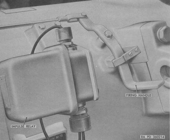
A manual firing handle was provided to the gunner on the right side of the gun mount. (Picture from TM 9-2350-200-12 Operation and Organizational Maintenance 90-mm Gun Full Tracked Combat Tank M47.)
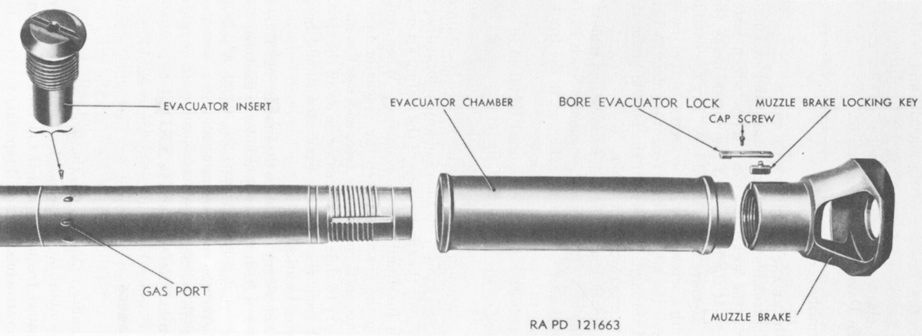
The bore evacuator and early single-baffle muzzle brake are shown disassembled. The complete gun weighed 2,650lb (1,200kg), while the tube weighed 1,750lb (794kg). The tube's estimated accuracy life was 700 equivalent full charge rounds. (Picture from TM 9-718A 90-mm Gun Tank M47.)
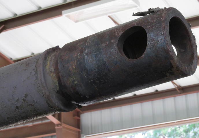
The cylindrical blast deflector used after the single-baffle muzzle brake is detailed here.
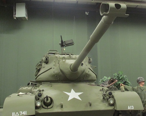
This is a late-production vehicle fitted with the T-shaped muzzle brake and solid periscope guards for the gunner and commander's cupola, which can be contrasted with the tanks above. The rangefinder blisters can be seen on the sides of the turret near the top.
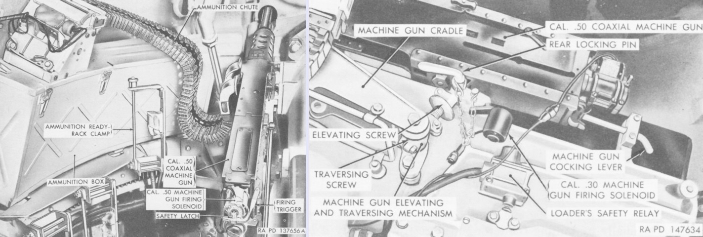
The coaxial machine gun cradle was on the left side of the combination gun mount. If a .50cal machine gun was mounted, the firing solenoid was installed on the machine gun as shown. If a .30cal machine gun was present, the firing solenoid was on the combination gun mount. The machine gun could be fired manually by pivoting the safety latch 90° forward and then pressing the firing trigger, which pushed the safety latch into the solenoid plunger. (Picture from TM 9-718A 90-mm Gun Tank M47.)
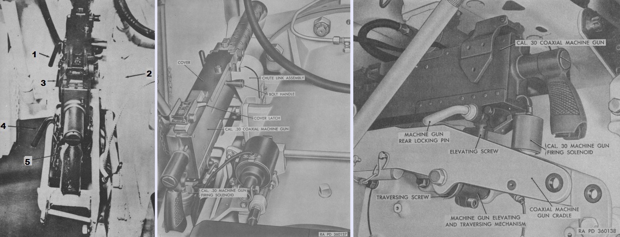
A .30cal coaxial machine gun can be contrasted with the .50cal. It could also be manually fired by pulling the trigger. The legend for the left image is: 1. Machinegun front locking pin. 2. Combination gun mount, M47 [sic]. 3. Coaxial machinegun. 4. Machinegun rear locking pin. 5. Elevating and traversing mechanism. (Picture from FM 17-78 Tank, 90-mm Gun, M47 and TM 9-2350-200-12 Operation and Organizational Maintenance 90-mm Gun Full Tracked Combat Tank M47.)
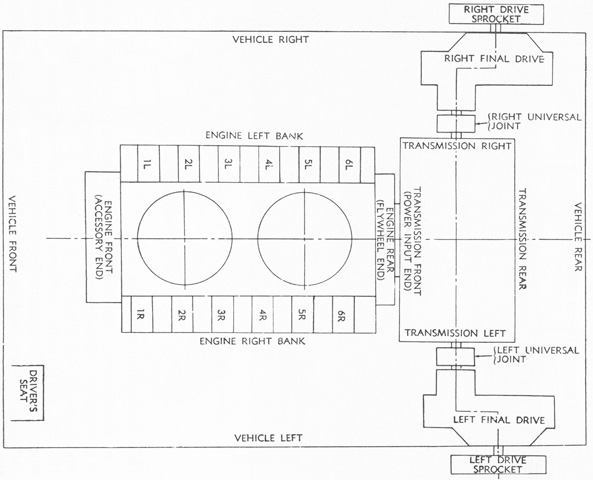
The orientation and nomenclature of the engine and power train is sketched above. The engine's firing order was 1R, 2L, 5R, 4L, 3R, 1L, 6R, 5L, 2R, 3L, 4R, and 6L. (Picture from TM 9-2350-200-12 Operation and Organizational Maintenance 90-mm Gun Full Tracked Combat Tank M47.)
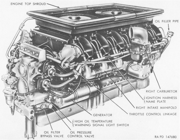
This is a right front view of the Continental AV-1790-5B engine. Each of the two cylinder banks was provided with its own carburetor. Bore and stroke for each of the 12 cylinders was 5.75" (14.6cm), yielding a displacement of 1,791.75in³ (29,361.4cm³). Maximum governed speed with full load was 2,800 rpm, and the dry weight with flywheel and transmission adapter was 2,505lbs (1,136kg). (Picture from TM 9-718A 90-mm Gun Tank M47.)
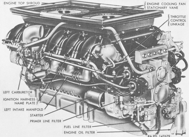
Including the flywheel assembly, the engine was 73.69" (187.2cm) long, 61.00" (154.9cm) wide, and 40.88" (103.8cm) tall. Compression ratio was 6.5:1. (Picture from TM 9-718A 90-mm Gun Tank M47.)
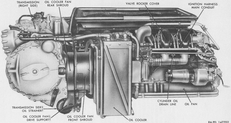
The engine is shown here with its oil coolers and the transmission mounted. (Picture from TM 9-718A 90-mm Gun Tank M47.)
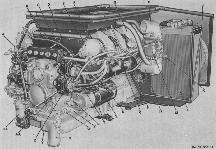
An AV-1790-7B engine is shown here with the oil coolers installed. A. Main engine fuel line quick-disconnect. B. Right magnetos. C. Engine wiring junction panel. D. Top shroud right front plate. E. Camshaft drive gear housing cover. F. Engine top shroud. G. Engine cooling fans [sic]. H. Carburetor intake elbow. J. Engine rear shroud. K. Degasser. L. Left oil cooler (transmission). M. Right carburetor. N. Hot spot manifold. P. Carburetor inlet flexible fuel line. Q. Intake manifold. R. Magneto vent line. S. Main generator. T. Ignition harness. U. Engine oil high temperature warning signal light switch. V. Oil pressure control valve. W. Oil filter bypass valve. X. Engine oil filter. Y. Oil cooler thermostatic bypass valve. Z. Tachometer sending unit. AA. Oil pump. BB. Fuel line filter. (Picture from TM 9-2350-200-12 Operation and Organizational Maintenance 90-mm Gun Full Tracked Combat Tank M47.)
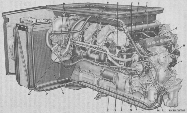
The AV-1790-7B seen from the opposite side. A. Degasser cable connections. B. Left cylinder bank. C. Throttle control linkage. D. Magneto to booster cables. E. Accessory case vent line. F. Governor control linkage. G. Engine wiring junction panel. H. Accessory drive shaft front support bearing cover. J. Accessory drive shaft cover. K. Left magnetos. L. Fuel line filter assembly. M. Fuel line filter drain cock. N. Fuel pump. P. Fuel pump to carburetor fuel line. Q. Engine oil cooler lines. R. Primer line filter. S. Primer lines. T. Starter. U. Right oil cooler. V. Oil cooler cradle. W. Carburetor inlet flexible fuel line. (Picture from TM 9-2350-200-12 Operation and Organizational Maintenance 90-mm Gun Full Tracked Combat Tank M47.)
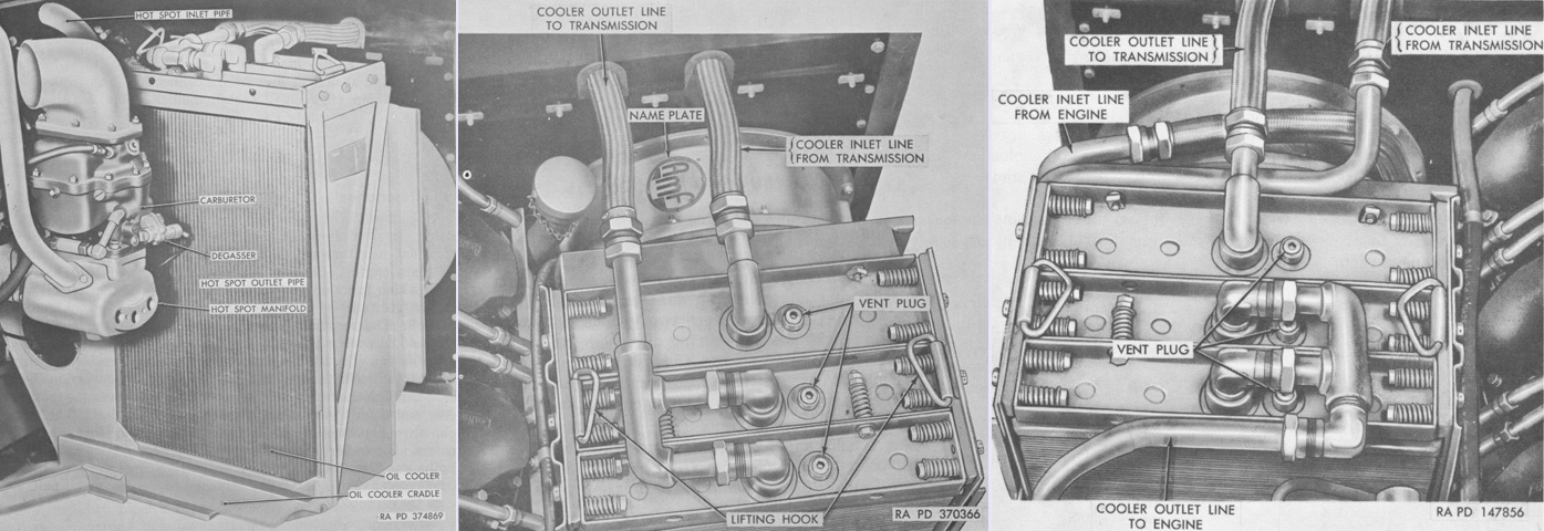
Each oil cooler had three cores. All three cores of the left oil cooler and the rear core of the right oil cooler were used for the transmission, while the main engine sufficed with the forward two cores of the right cooler. A fan was mounted between each oil cooler and the engine rear shroud. The left oil cooler is shown in the left and center views, while the right is shown in the right image. (Picture from TM 9-2350-200-12 Operation and Organizational Maintenance 90-mm Gun Full Tracked Combat Tank M47.)
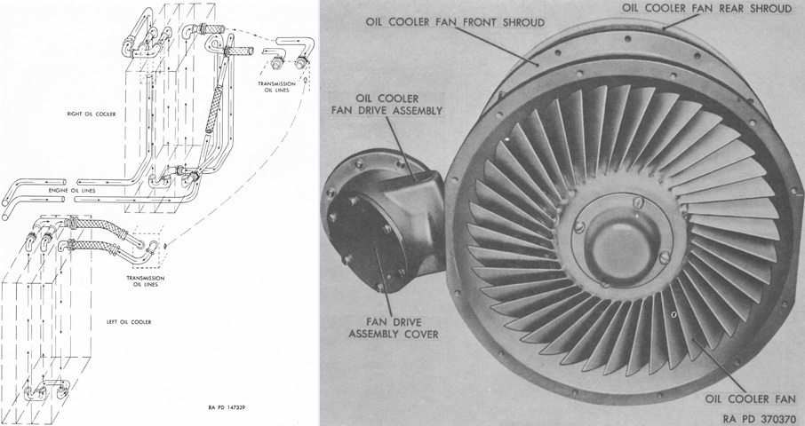
A schematic of oil flow through the coolers is drawn on the left, and an oil cooler fan is on the right. The fans drew air through the louvres in the top deck, through the oil cooler cores, and over the transmission and out through the louvres in the rear of the top deck. Heated air was prevented from recirculating through the cores by the engine rear shroud. (Picture from TM 9-2350-200-12 Operation and Organizational Maintenance 90-mm Gun Full Tracked Combat Tank M47.)
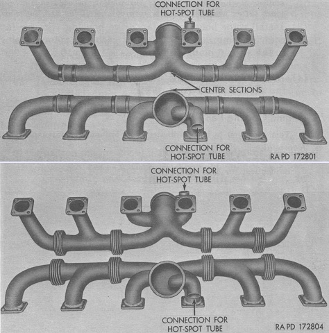
The difference in construction of the early AV-1790-5B's exhaust manifolds and those found in later engines is illustrated above. The two types were interchangeable. (Picture from TM 9-2350-200-12 Operation and Organizational Maintenance 90-mm Gun Full Tracked Combat Tank M47.)
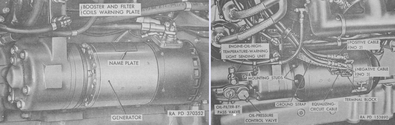
The 150 ampere Eclipse-Pioneer generator on the left can be contrasted with the AV-1790-7B's 300 ampere Jack and Heintz model on the right. Both were 24-volt, 4-pole, 4-brush, field regulated units using interpole and compensating windings. (Picture from TM 9-2350-200-12 Operation and Organizational Maintenance 90-mm Gun Full Tracked Combat Tank M47.)
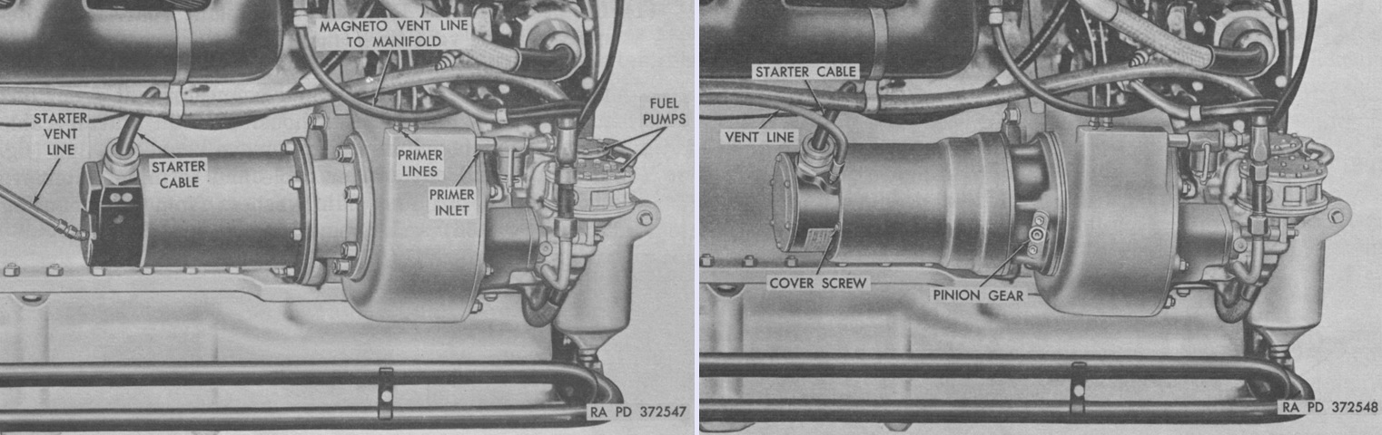
Engines could be found with either an Eclipse-Pioneer starter, as on the left, or a Jack and Heintz starter, as on the right. Both were waterproof, 24-volt types that used series-parallel wound, 4-pole motors with four brushes. The Eclipse-Pioneer weighed 31.5lb (14.3kg) and could produce 400lb-ft of torque. The Jack and Heintz starter weighed 34lb (15kg) and put out 800-900lb-ft of torque. (Picture from TM 9-2350-200-12 Operation and Organizational Maintenance 90-mm Gun Full Tracked Combat Tank M47.)
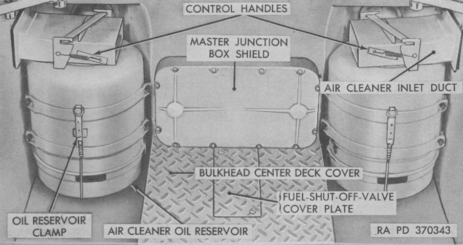
The engine's air cleaners were installed at the rear of the crew compartment. The control handles permitted changing whether air was drawn in from the crew compartment (handle in the up position) or from the engine compartment (handle in the down position). Typically the handles were kept down. (Picture from TM 9-2350-200-12 Operation and Organizational Maintenance 90-mm Gun Full Tracked Combat Tank M47.)
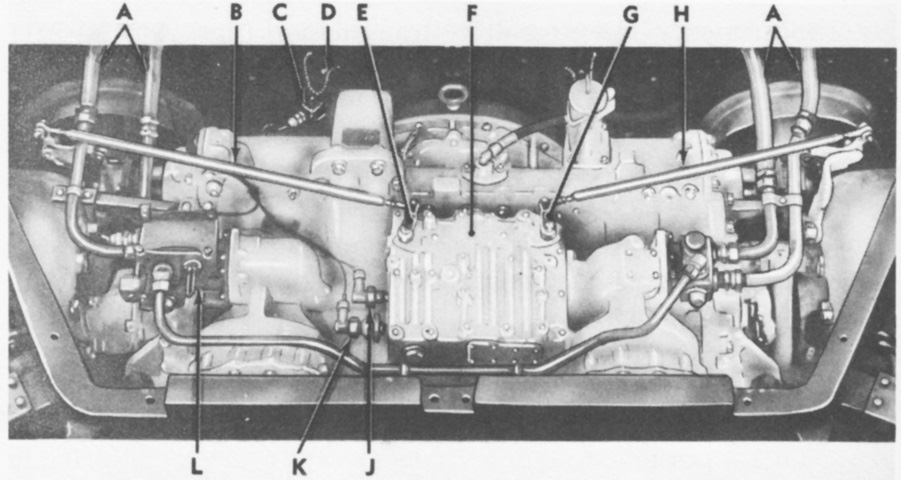
The CD-850-4 cross-drive transmission is shown here installed in the hull. This single unit took care of power transmission, steering, and braking. It weighed 2,946lb (1,336kg) dry; was 30" (76cm) long, 40.375" (102.55cm) tall, and approximately 40" (100cm) wide over the drive flanges. A. Transmission oil cooler lines. B. Steering control rod. C. Speedometer sending unit. D. Spark plug access opening cover. E. Steering control lever. F. Transmission valve body. G. Shifting control lever. H. Shifting control rod. J. High-oil-temperature-warning-signal-light switch. K. Low-oil-pressure-warning-signal-light switch. L. Transmission oil cooler fan controller. (Picture from TM 9-718A 90-mm Gun Tank M47.)
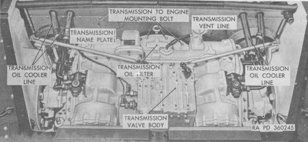
A later model of transmission can be contrasted with the image above. (Picture from TM 9-2350-200-12 Operation and Organizational Maintenance 90-mm Gun Full Tracked Combat Tank M47.)
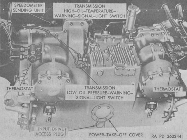
The rear of the transmission is better seen outside of the hull. (Picture from TM 9-2350-200-12 Operation and Organizational Maintenance 90-mm Gun Full Tracked Combat Tank M47.)
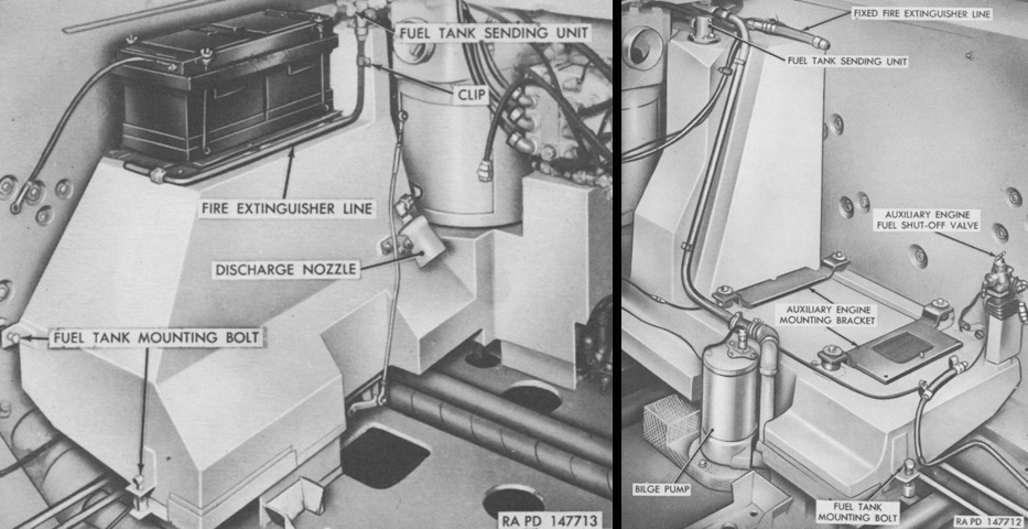
The left and right side fuel tanks are shown on the left and right, respectively. In addition to two 12-volt batteries contained in the forward part of the engine compartment, two more 12-volt batteries were mounted on the left fuel tank as seen here. Nozzles for the left rear and right fire extinguisher lines are absent. (Picture from TM 9-718A 90-mm Gun Tank M47.)
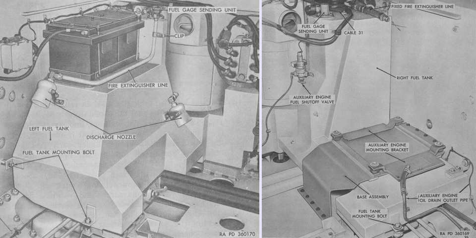
Fuel tanks in a later production tank are shown here. Note the revised base for the auxiliary engine on the right. (Picture from TM 9-2350-200-12 Operation and Organizational Maintenance 90-mm Gun Full Tracked Combat Tank M47.)
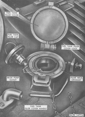
A fuel filler was available in the deck to the right and left rear of the turret. The fuel tank filler covers were provided with locks to prevent enemy troops from dropping hand grenades into the fuel tanks. (Picture from TM 9-2350-200-12 Operation and Organizational Maintenance 90-mm Gun Full Tracked Combat Tank M47.)
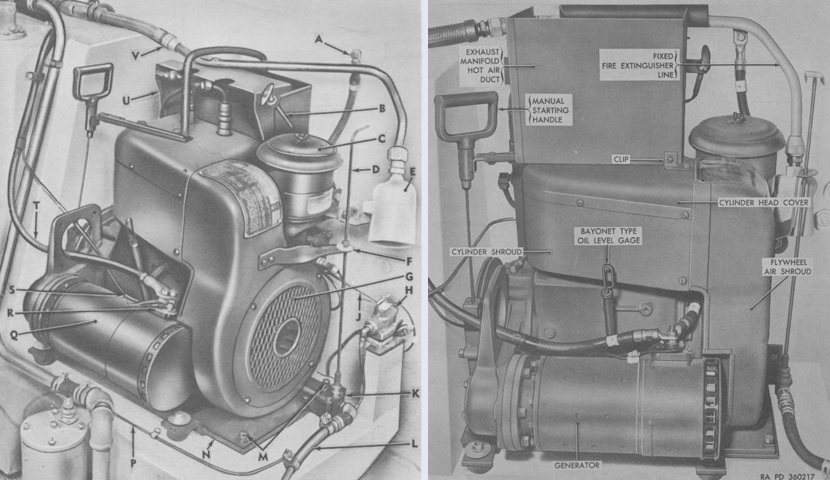
An auxiliary engine and generator were mounted behind the right main engine fuel tank. The auxiliary engine could accept fuel from either main engine fuel tank, and was a Wisconsin TFT 13.6hp, air-cooled, two-cylinder, constant speed (2,800rpm), 4 cycle gasoline engine. Its bore and stroke were both 3.25" (8.26cm). It could be started electrically via the tank's electrical system, or via a pull-type manual starting handle. The generator was an Eclipse-Pioneer EC-30E00-3-A 150-ampere, 24-volt, 4-pole, 4-brush, field-regulated unit using interpole and compensated windings, the type also used by the main engine. Installations in an early and a late tank are shown on the left and right, respectively. The legend for the left image is: A. Generator ground cable. B. Choke control cable. C. Air cleaner. D. Drain valve handle. E. Fire extinguisher nozzle. F. Drain valve dial. G. Air intake screen. H. Fuel shut-off valve. J. Fuel line, shut-off valve to pump. K. Drain valve. L. Drain outlet pipe. M. Mounting plate attaching screw. N. Engine mounting plate. P. Fuel line from tank. Q. Generator. R. Generator terminal block. S. Equalizer circuit cables (61) and (478). T. Generator positive cable. U. Heat deflector. V. Fire extinguisher line connector. (Picture from TM 9-718A 90-mm Gun Tank M47 and TM 9-2350-200-12 Operation and Organizational Maintenance 90-mm Gun Full Tracked Combat Tank M47.)

Nomenclature of the suspension components is given in this image. (Picture from TM 9-718A 90-mm Gun Tank M47.)
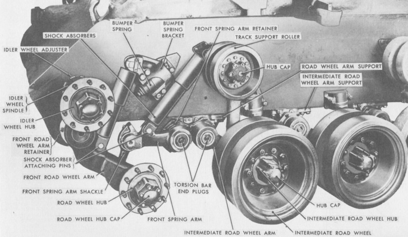
The adjusting idler and front road wheels have been removed, revealing the connection between them. As the front road wheel encountered ground undulations or obstacles, the adjusting idler wheel was moved in response to the deflection imparted to the front road wheel. Track tension could be adjusted via the idler wheel adjuster. (Picture from TM 9-718A 90-mm Gun Tank M47.)
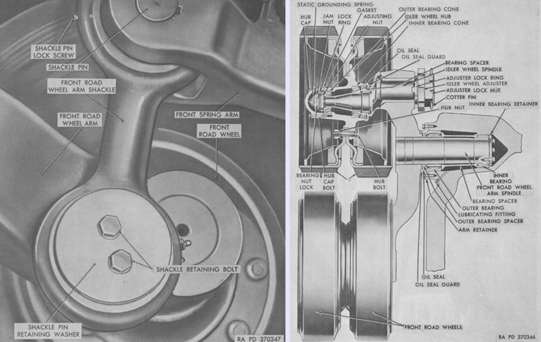
On the left, a view of the inside of a front road wheel reveals the connections between the front spring arm, front road wheel arm shackle, and front road wheel arm. A cross-section of the idler wheel and front road wheel is drawn on the right. (Picture from TM 9-2350-200-12 Operation and Organizational Maintenance 90-mm Gun Full Tracked Combat Tank M47.)
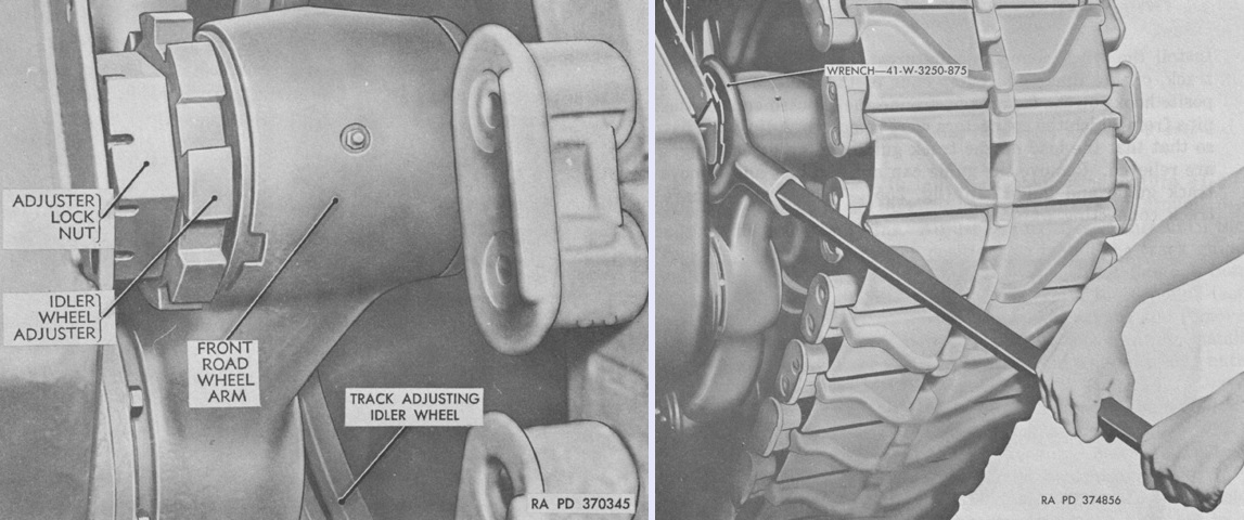
Track tension was adjusted by backing off the adjuster lock nut by ~.5" (~1.3cm) after removing its cotter pin. The idler wheel adjuster also had a serrated lock ring that needed separating to permit the adjuster to rotate. Once done, the idler wheel adjuster could be turned with a bespoke wrench. (Picture from TM 9-2350-200-12 Operation and Organizational Maintenance 90-mm Gun Full Tracked Combat Tank M47.)
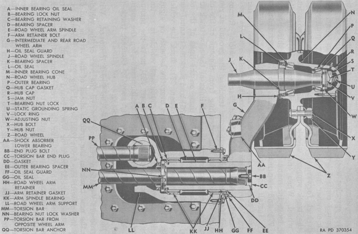
A cross section of an intermediate road wheel is drawn. (Picture from TM 9-2350-200-12 Operation and Organizational Maintenance 90-mm Gun Full Tracked Combat Tank M47.)
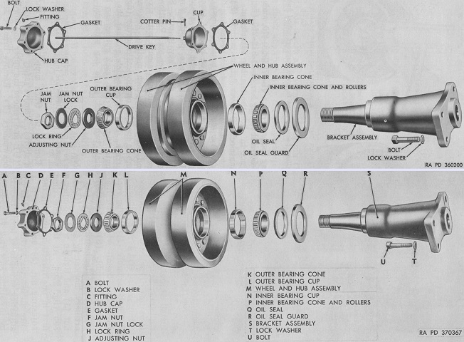
In tanks with mechanical speedometer and tachometers, the front left track support roller featured the speedometer drive key in its hub, shown in the top image. A roller without this key is illustrated at the bottom. (Picture from TM 9-2350-200-12 Operation and Organizational Maintenance 90-mm Gun Full Tracked Combat Tank M47.)
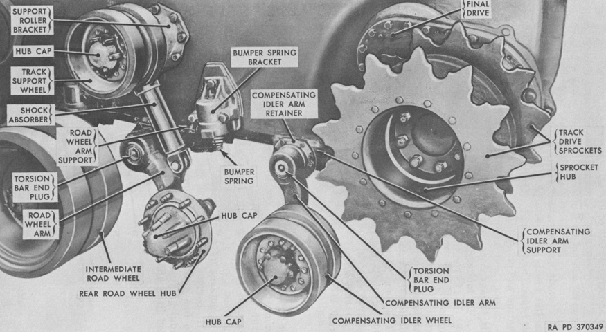
Components of the left rear suspension are labeled with the track and rear road wheel removed. (Picture from TM 9-2350-200-12 Operation and Organizational Maintenance 90-mm Gun Full Tracked Combat Tank M47.)
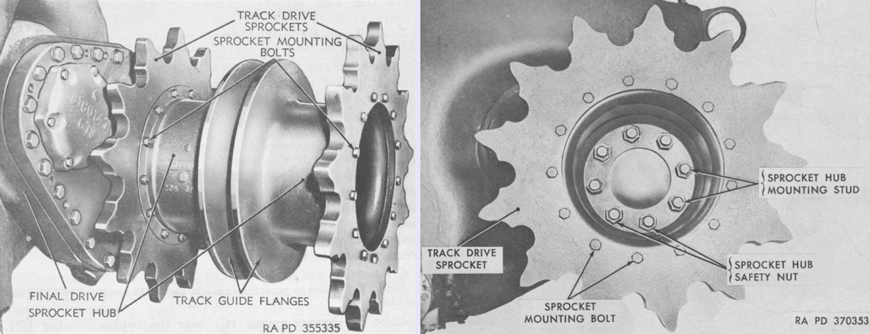
A drive sprocket is detailed in these images. (Picture from TM 9-2350-200-12 Operation and Organizational Maintenance 90-mm Gun Full Tracked Combat Tank M47.)
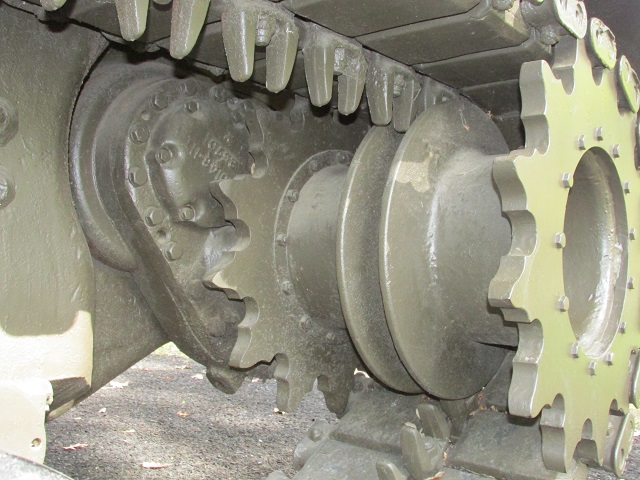
The final drives on the M47 were at a similar angle to those found on the M46.
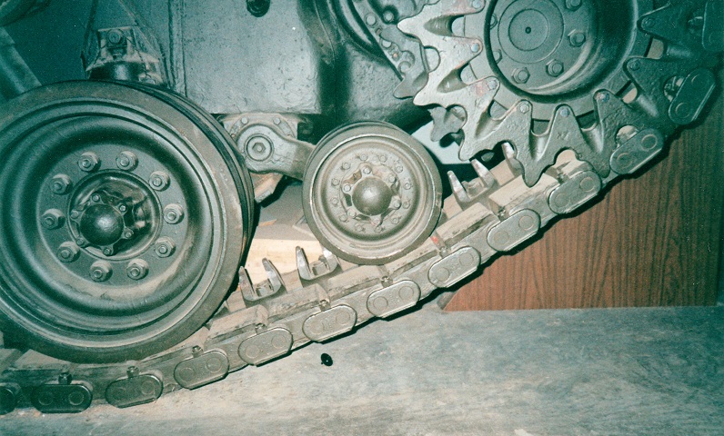
This detail shows the auxiliary track tensioning idler behind the number 6 road wheel. The addition of this wheel helped keep the track from becoming excessively slack and thereby helped prevent thrown tracks.
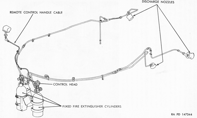
Three fixed fire extinguisher cylinders were mounted between the drivers. These could be actuated from outside the tank via the remote control handle found behind the assistant driver's hatch, or inside by the pull handle on the left-side cylinder. In addition, a 5lb (2.3kg) CO2 portable extinguisher was mounted in the driver's compartment and in a stowage box in the turret bulge. (Picture from TM 9-718A 90-mm Gun Tank M47.)
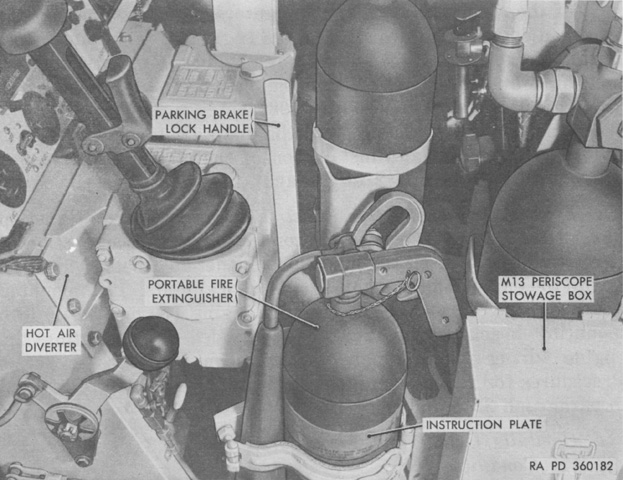
The portable extinguisher in the driver's compartment is shown here. (Picture from TM 9-2350-200-12 Operation and Organizational Maintenance 90-mm Gun Full Tracked Combat Tank M47.)
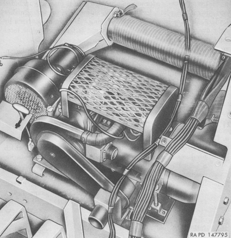
The Stewart-Warner 978M-R24 personnel heater was retained from the M46A1. It was installed under the driver's instrument panel, as shown. (Picture from TM 9-718A 90-mm Gun Tank M47.)
